Question about MMA8452Q accelerometer

Hi all,
I have a personal project on arduino Uno from a makeBlock kit that would use a MMA8452Q vellman accelerometer.

the accelerometer specifications state that the vcc inputs accepts between 3 and 5 volts, the uno card has a 5 volts output.

Am I correct to understand that the accelerometer component has an incorporated regulator ?

From your experiences, are those materials compatible ? if not is there a way to make them so ? otherwise what accelometer should I use ?

I'm quite beginner of this matter, so any help would be really appreciated.

Yes it does and it also has level shifters for the I2C signals.
You can use it with your 5V Uno

Schematic from Velleman

Thanks you for your help,
So if I'm right, I can connect both without issue? (I already have an adaptator from RJ25 to classic wires.
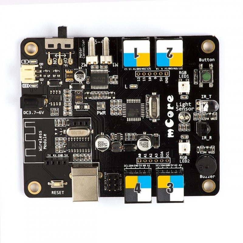
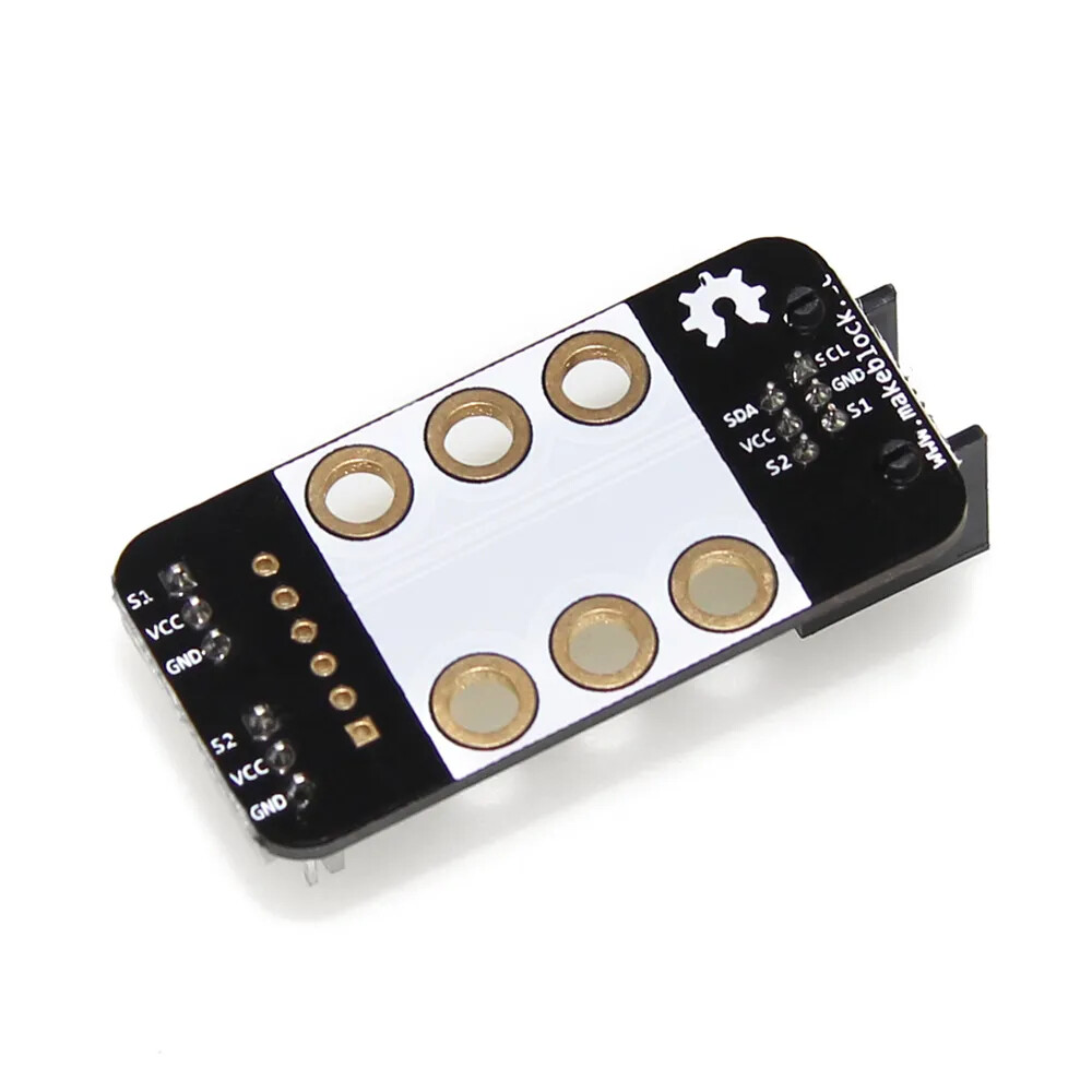
If you want to see here is my card and the sensor :

I will try next week and I will keep you udpated :slight_smile:

As I already said, you can connect the mma8452q to an Uno but I know nothing about that other boardthat you show. What is it? Do you have a datasheet and schematic?

I already have an adaptator from RJ25 to

What are these for?

I have the card I show you in the previous text, it can be programmed like an Uno and I have an adaptator to use the card as an Uno.

On the card these are the output :SCL SDA GND 5V S1 S2.
And on the sensor : VCC 3.3V GND SCL SDA SA01 INT1 INT2.

Then connect VCC to 5V, SCL to SCL, SDA to SDA, and GND to GND.
The Uno does not have S1 or S2 so I don't know what they are.
Do you have a schematic for that card?

Here is the schematic:

I would use RJ25 Port 2.
S1 is Uno D9 and S2 is Uno D10. If needed, you can connect INT1 and INT2 to those pins.

Thank you for your help!
So if I m right the SA01 and 3.3V does not need to be connected?
I will recive all the components soon, and I will keep you updated.

That is correct.

So, I try to connect everything as you say, and runnig the card with this code:

#include <Wire.h>
#include <Adafruit_MMA8451.h>
#include <Adafruit_Sensor.h>

Adafruit_MMA8451 mma = Adafruit_MMA8451();

void setup() {
  Serial.begin(115200);
  Wire.begin();  // start I2C

  if (!mma.begin()) {
    Serial.println("❌ sensor MMA8451 not detected");
    while (1);  // Stop when non sensor found
  }

  mma.setRange(MMA8451_RANGE_2_G); 
  Serial.println("âś… sensor ready.");
}

void loop() {
  mma.read();  // read sensor

  // fetch values
  Serial.print("X: "); Serial.print(mma.x);
  Serial.print(" | Y: "); Serial.print(mma.y);
  Serial.print(" | Z: "); Serial.print(mma.z);
  Serial.println(" (mg)");

  delay(100);  
}

And it didn't work, I get the error stating the card is not detected.
If you want to see here is the compnents:

Time to run the I2C_scanner sketch.
Click on Files->Examples->Wire->i2c_scanner and open the file and uploade.

Run the sketch and see if it finds the accelerometer.
Should find it at 1C.

Also, I'm not sure that the 8451 library would work with the 8452Q, better to use the Sparkfun 8452Q library.

You will need to set the I2C address to 0x1C in thta library.

1 Like

I uploaded and ran the i2c_scanner.ino, unfortunetly I get an 'No I2C devices found' message. It really looks like the material can't be detected, however I doubled checked the wiring and found no mistake, I think I will need a multimeter to check tensions if the sensor.

Yes most likely a connection problem. I see that the adaptor board was not designed for the jumper wires, are you sure that ar making a good connection?

Disconnect everything!

Those white connectors do not have SCL and SDA on them.
See images below.

You are right, the white part isn't useful here, and by connecting to the correct output ... IT WORKS !
Thanks a lot for your valuable help, I'm currently programming a python
script to read and graph all the data.

Glad you got it working.
Have a nice day!

1 Like

This topic was automatically closed 180 days after the last reply. New replies are no longer allowed.