Question: Reed-Relay not responding to OUTPUT pins but does respond on 3v3 pins

Good day everybody.

I have been struggling with this small issue. I hope from someone to give me an answer or at least a direction. Since this is Electronics related I think I placed it in the right forum topic, but if I’m wrong please correct me.

Problem:

I want to power a reed-relay via an ESP32. The reed-relay works fine if I power it directly via the 3v3 pin of the ESP32. However, it does not work if I try to power it up via another pin with OUTPUT pin mode set to HIGH.

Description:

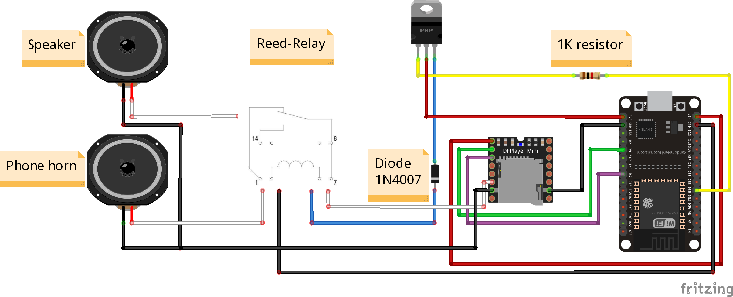
I am creating a puzzle game that involves an mp3 player. I want to be able to relay the audio signal to a telephone horn if a phone message is playing. If not, I want to be able to play a moody background sound via a speaker. So, my ESP32 must be able to relay the audio either to the phone horn or the speaker.

To make this possible I first tried a regular relay switch. However, the clicking noise of the switch was bothering me and I looked for a more silent solution. After a little search I decided to choose a reed-relay. Technical specifications can be found here:

https://asset.conrad.com/media10/add/160267/c1/-/en/001205873DS02/datablad-1205873-standexmeder-electronics-dip05-1c90-51l-reedrelais-1x-wisselcontact-5-vdc-05-a-10-w-dip-8.pdf

If I read the power specification correctly, it should work with 3v3 at 25mA. Slightly below the 40mA that the ESP32 can deliver.

My technical setup now looks like this:

But no matter which digital output pin I use, the reed-relay does not power up and work as intended. To make sure that my ESP32 is not damaged, I replaced the reed-relay with a simple resistor and LED. I see the diode shining once the output pin is powered up.

What am I overlooking or doing wrong? Is the power output of a digital pin lower than 3v3 at 40mA?

My thanks in advance for everybody that can point me in the right direction.

Additional Stuff:

Even though I don’t think it is program related, the code below can be used to test the reed-relay:

// Command module running on an ESP32.
#include <SoftwareSerial.h>
#include "DFRobotDFPlayerMini.h"

// MP3 initialization.
#define MP3_RX_PIN              5     // GPIO5/D1
#define MP3_TX_PIN              4     // GPIO4/D2
#define MP3_SERIAL_SPEED        9600  // DFPlayer Mini suport only 9600-baud
#define MP3_SERIAL_BUFFER_SIZE  32    // Software serial buffer size in bytes, to send 8-bytes you need 11-bytes buffer (start byte+8-data bytes+parity-byte+stop-byte=11-bytes)

// Pin initialization.

#define Audio_Pin               32    // GPIO18. Pin for controlling the Reed-Relay that handles the audio output.

// SoftwareSerial and MP3player declaration.
SoftwareSerial mp3Serial; // RX, TX
DFRobotDFPlayerMini mp3;

void setup() {
  // put your setup code here, to run once:
  Serial.begin(9600);
  mp3Serial.begin(MP3_SERIAL_SPEED, SWSERIAL_8N1, MP3_RX_PIN, MP3_TX_PIN, false, MP3_SERIAL_BUFFER_SIZE, 0);

  delay(500);

  if (!mp3.begin(mp3Serial)) {  //Use softwareSerial to communicate with mp3.
    Serial.println(F("DFPlayer unable to begin:"));
    while (true);
  }
  Serial.println(F("DFPlayer Mini online."));

  pinMode(Audio_Pin,OUTPUT);

  // mp3 Config Settings
  mp3.setTimeOut(400); //Set serial communictaion time out 400ms 
  mp3.volume(30);  //Set volume value (0~30).
  mp3.EQ(DFPLAYER_EQ_NORMAL);
  mp3.outputDevice(DFPLAYER_DEVICE_SD);

  mp3.loop(1);
}

void loop() {
  digitalWrite(Audio_Pin,HIGH);
  delay(500);
  digitalWrite(Audio_Pin,LOW);
  delay(500);
}

Thanks for the full and detailed posting.

I suspect the ESP32 pins are only rated for a few mA, its a fast processor, not a relay driver. Normally you'd use a transistor or MOSFET to drive a load that takes current more than a few mA.

However the most important detail is that any inductive load like a motor or relay must have a free-wheel diode across it to prevent high voltage spikes being generated when switching it. You may have fried your ESP32's pin already.

Googling "Arduino relay circuit" ought to pull up lots of suggestions, for instance: https://www.electroschematics.com/arduino-control-relay/

Note the orientation of the diode - it conducts when the transistor switches off to allow the relay winding current to gracefully ramp down (if you try to stop the current suddenly, the winding will generate as much voltage as is necessary to keep it flowing, 100's or even 1000's of volts are possible without the diode - bad news!

From where do you conjure that figure?

(Hint: It is not an Arduino ATmega! :astonished:)

However, when controlled as a defined OUTPUT of a microcontroller, the output FETs will function to the same effect as the diode.

That is to say, when it is switched from HIGH to LOW, the low side driver will be switched on and carry the current as it decays. Predicated of course, that the said current is within the capability of both drivers.

Are you talking about the mechanical/sound click directly from the relay? Or do you mean the click generated in the speakers when the relay switches? If the latter, I suspect switching to a reed relay won't help.

Yes it is the actual mechanical clicking of the relay that I do not want. You are right that you hear a click sound from the speaker once you power it on or off, but that does not bother me.

At least not yet, but that may be a question for the forum for another day.

@MarkT and @Paul_B thanks for the feedback so far. As I re-read the documentation I do think you are right. That the pins on the ESP32 are supplying much less current. Plus that the pins should be mainly for signal processing, not for actually powering stuff.

I'll admit that I worked a lot more with the Arduino boards and that this is my first experience with the ESP32.

Ok, back to the drawing board...

If I look at the schematics given by the example I think I can create something with this:

relay_schematic

I need to order some transistors and that diode that is mentioned. But first I think I'll redraw a new solution in Fritzing. Once I done that, would you be so kind to review it and see if I forgot something or did something wrong?

The link is broken!

For the transistor, an ordinary BJT like BC337 or MOSFET like 2N7000 should be fine. For the diode, 1N4001 or similar.

I saw it. I corrected the link to an actual image.

Looks OK.

Its better to connect the pushbutton between the Arduino pin and ground and set the pin to INPUT_PULLUP. The 10K is then not required. (The pin will of course read LOW when the button is pressed. This is the normal & sensible way.)

Just realised, your diagram shows the speaker, phone horn and reed relay connected together (white wire), so you can't switch between them. You need a SPDT relay for that, and most reed relays I have seen are only SPST.

@PaulRB you are right, the pullup could solve that. However, I don't think I will need that button in my solution. Instead I think about solving this completely in the program itself. Using extremely simplified pseudo-code like:

If (phone is on and event happened) {
    digitalWrite(relayPin, HIGH) // so the reed-relay will be set to high.
}
else {
    digitalWrite(relayPin, LOW) // to play a moody background sound.
}

I'll start drawing something and post it here. I'm having a little bit of a hard time with my logic sense how to relay that audio signal through the reed-relay. I also can't really escape the feeling that I'm overcomplicating things.

Should be digitalWrite()!

Ouch. Thanks for that comment. No the speaker line and horn line are connected to two different "exits" of the reed-relay. They are not connected. If the power to the reed-relay is off, the audio is sent to the horn. If the power is high, the sound will be relayed to the speaker. Schematic:

reed-relay-layout

I'll adjust that image for clarity. My apologies for the confusion.

So your reed relay is SPDT? Are you certain?

EDIT: just googled for "reed relay SPDT" and there are plenty of examples, not rare like I thought.

OK. First of all thank to you all for thinking along. I took all your input and put it in a Fritzing image to check with you all to see if this might be a solution. This is as far as I came so far, waiting for further feedback to perfect it.

Since the Reed-Switch was not available in Fritzing I pasted it afterwards. For the MOSFET or Transistor Collector I made use of the 3v3 pin of the ESP32. Is that handy or should I make use of a separate power source? The 3v3 seemed to work in earlier settings.

I also incorporated the 1N4007 diode as a safety measure against the high voltage.

If you good people see anything that's questionable please comment. Since this is kind of new to me please don't be harsh but definitely critical.

My thanks again for all your input.

A hand drawn schematic is much better than any Fritzing. As you're finding out now there are quite some limitations to Fritzing and the worst of all is that despite its fancy icons and pretty colors it tends to yield a kind of digital spaghetti that's just confusing to read.

Aside from that, looks like you've got that transistor and diode wired up wrong. Compare it to the schematic earlier int he thread.

I never understood why people insist on using mains voltage rated parts for low voltage circuits.
Maybe the more/bigger = better syndrome.

That diode won't see any more than the supply voltage so the 1N4001 to 1N4004 range is better suited for the job than an 1N4007.
Leo..

Hi, @niels_v
As mentioned, it is time for you to start drawing circuit diagrams with standard symbols and topology.
A hand drawn diagram with component names and pin labels will be fine.

Can you also post link to specs/data of your relay please?

Thanks.. Tom... :smiley: :+1: :coffee: :australia:

The NC contact is simply non-magnetic.
https://uk.farnell.com/productimages/large/en_GB/2453626-40.jpg

And it may surprise you to realise that a 1N4148/ 1N914 is rated at 300 mA continuous forward current and 100 V so is a smaller, generally cheaper but perfectly suitable alternative in most cases.

Yes, the 1N4148 has been my go-to small signal diode for as long as I can remember.
Wouldn't use it for more than 100mA continuous though, but perfect for small relays.
Leo..