I looked in the datasheet and can't find any way to set the current limit for the board. I 'm not worried about the PS because the current display will show any current (I can see even very small currents when I'm running dc motors with the motor shield) and so far I haven't seen ANY current with this stepper driver. When I ran both steppers using my DK Motor Shield and the Adafruit Motor Library MultiStepper example , the current ranged from 0.2A to 0.6A depending on how high I set the speed parameter.
raschemmel:
I looked in the datasheet and can't find any way to set the current limit for the board.
Have you looked at the Pololu web page? Does your board have the same test point for measuring the voltage that is a proxy for the current?
What angle is the potentiometer at on your board?
...R
I have the trim pot (I tried different positions with no effect) but I couldn't find anything about any test point on the pololu site.
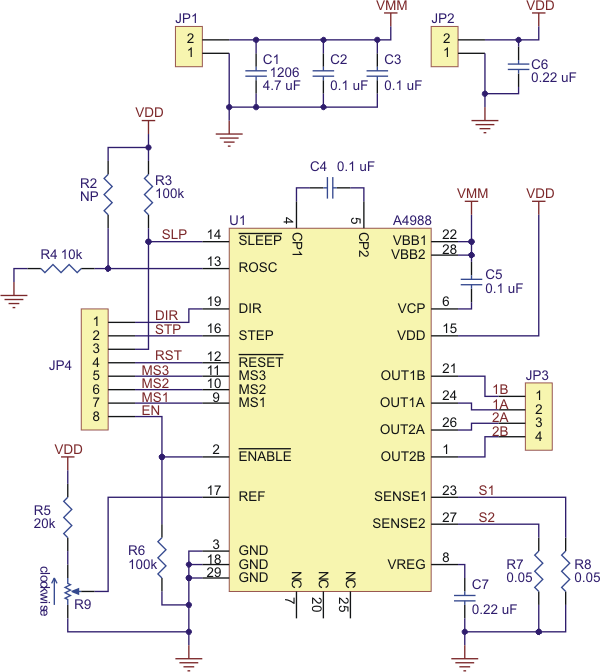
Extract from the section on current limiting on this page
Another way to set the current limit is to measure the voltage on the “ref” pin and to calculate the resulting current limit (the current sense resistors are 0.05?). The ref pin voltage is accessible on a via that is circled on the bottom silkscreen of the circuit board. The current limit relates to the reference voltage as follows:
And you can see it in the photo of the board with the coin. The test point is accessible from both sides of the board.
That makes us even for me losing the loop() code off the bottom of my earlier post ![]()
...R
this is the one I have:
http://www.ebay.com/itm/A4988-RAMPS-Pololu-StepStick-stepper-motor-driver-with-heatsink-Prusa-Mendel-/201084529309?ssPageName=ADME:L:OU:US:1120
raschemmel:
this is the one I have:
I know. I think you posted that link before. But the image only shows one side with the heatsink hiding everything and from your own photo you haven't put the heatsink on yet - but your photo is not very clear.
Can you post two clear photos, one of each side of your stepper driver board.
I hope you read back through this Thread before you lash out at another newbie ![]()
![]()
...R
I hope you read back through this Thread before you lash out at another newbie smiley smiley
Are you suggesting I'm a heartless bastard with no mercy ? XD
raschemmel:
Are you suggesting I'm a heartless bastard with no mercy ?
Certainly NOT. Just a guy with a non-working stepper driver ![]()
...R
Are you suggesting I'm a heartless bastard with no mercy ?
Certainly NOT. Just a guy with a non-working stepper driver smiley
Your too kind... XD
I got my new stepper driver (same kind) and it works.
After verifying it works with several different programs I turned off the power and swapped it with the bad one and it's still bad.
No harm in trying I guess.
Anyway I still need one more driver because I have two motors so should I spend another $4.20 (free shipping) or should I get something else ?
This is what I have
http://www.ebay.com/itm/201084529309
Attached is the sketch I'm running from the Accelstepper Library , modified to add a variable called mposition:
one_stepper_Microstep_Sixteenth_step_Accel_Speed_Position_Move_.ino (1.19 KB)
raschemmel:
should I spend another $4.20 (free shipping) or should I get something else ?
Now that you know that those drivers are capable of working I believe you are faced with an economic decision rather than a technical one. Only you can balance your wish to save money against the risk of buying another dud (assuming you did not accidentally break the first one).
...R
I just found this post that shows how to use the Stepper Library with an L293 (I have some of those)
raschemmel:
I just found this post that shows how to use the Stepper Library with an L293 (I have some of those)
Arduino Code | Arduino Lesson 16. Stepper Motors | Adafruit Learning System
I presume you are just teasing and you really know how much better the A4988 is ???
...R
Yes and No.
I know that both allow you to set the speed, but I guess I really don't know how much better the A4988 is.
Maybe you should enlighten me since I am feeling somewhat ignorant about it at the moment.
Pretend I am a Newbie.... XD
raschemmel:
Yes and No.
I know that both allow you to set the speed, but I guess I really don't know how much better the A4988 is.
Maybe you should enlighten me since I am feeling somewhat ignorant about it at the moment.
Pretend I am a Newbie.... XD
But you are not really a newbie .... (I hope this is not a piss-take)
The proper stepper driver boards allow you to limit the current in the motor so they can use high voltages without damaging the motor. High voltages allow the current to reach its maximum more quickly in the face of the inductance of the motor. That means more torque at higher speeds.
The proper boards just need step and direction signals which greatly reduces the computation load on the Arduino as well as the number of pins needed per motor. And the proper boards usually allow for microstepping.
...R
Low Current Microstepping. Intended for applications where the minimum on-time prevents the output current from regulating to the programmed current level at low current steps. To prevent this, the device can be set to operate in Mixed decay mode on both rising and falling portions of the current waveform. This feature is implemented by shorting the ROSC pin to ground. In this state, the off-time is internally set to 30 ?s.
Internal PWM Current Control. Each full-bridge is controlled by a fixed off-time PWM current control circuit that limits the load current to a desired value, ITRIP . Initially, a diagonal pair of source and sink FET outputs are enabled and current flows through the motor winding and the current sense resistor, RSx. When the voltage across RSx equals the DAC output voltage, the current sense comparator resets the PWM latch. The latch then turns off the appropriate source driver and initiates a fixed off time decay mod The maximum value of current limiting is set by the selection of RSx and the voltage at the VREF pin. The transconductance function is approximated by the maximum value of current limiting, ITripMAX (A), which is set by ITripMAX = VREF / ( 8 ? RS) where RS is the resistance of the sense resistor (?) and VREF is the input voltage on the REF pin (V). The DAC output reduces the VREF output to the current sense comparator in precise steps, such that Itrip = (%ITripMAX / 100) × ITripMAX (See table 2 for %ITripMAX at each step.) It is critical that the maximum rating (0.5 V) on the SENSE1 and SENSE2 pins is not exceeded. Fixed Off-Time. The internal PWM current control circuitry uses a one-shot circuit to control the duration of time that the DMOS FETs remain off. The off-time, tOFF, is determined by the ROSC terminal.
The ROSC terminal has three settings: ? ROSC tied to VDD — off-time internally set to 30 ?s, decay mode is automatic Mixed decay except when in full step where decay mode is set to Slow decay ? ROSC tied directly to ground — off time internally set to 30 ?s, current decay is set to Mixed decay for both increasing and decreasing currents, except in full step where decay mode is set to Slow decay. (See Low Current Microstepping section ROSC through a resistor to ground — off-time is determined by the following formula, the decay mode is automatic Mixed decay for all step modes. tOFF ? ROSC ? 825 Where tOFF is in ?s.
The maximum value of current limiting is set by the selection of RSx and the voltage at the VREF pin. The transconductance function is approximated by the maximum value of current limiting, ITripMAX (A), which is set by ITripMAX = VREF / ( 8 ? RS) where RS is the resistance of the sense resistor (?) and VREF is the input voltage on the REF pin (V). The DAC output reduces the VREF output to the current sense comparator in precise steps, such that Itrip = (%ITripMAX / 100) × ITripMAX
The chip is a fine pitch surface mount and there's no way I can measure the voltage on the Vref pin. I should be able to locate the 0.05 ohm sense resistors and measure the voltage on those.
http://forum.olymega.org/viewtopic.php?f=66&t=85&start=20#p424
Current = 2.5xVref
So 400mV gives you 1A
Vref is a lot easier to measure because it is a DC voltage. See that little through-hole between the capacitor and the A4988 chip? Measure it there while adjusting the pot.
I'm changing out a resistor on mine, because most of them come with R5 -way- too small, so most of the adjustment on R9 is compressed at the CCW end.
Details of all of this at the link above.
Oh, yeah. If you use Vref as a measure to set the current, the motors do not have to even be attached, and the board does not have to be enabled.
See that little through-hole between the capacitor and the A4988 chip? Measure it there while adjusting the pot.
I don't think we have the same board . See attached photo of mine.


Well... Vref is the wiper arm of the trimpot, so you should be able to put an alligator clip on a metal screwdriver while adjusting it.