RC with HC-12 ---- Control two motors and a led

Hi everyone,

I work on a project that will enable me to control simple RC car which moves forward/backwards & left/right and turning a LED laser on or off to play with my cat:). I use HC-12 as the TRX module and everything works well except the simplest part, the led. I use a joystick to control the directions and a common switch(I tried the joystick switch too) to turn on/off the 5v led. Normally, when I push the button it turns on the led but when I released the button it does not completely off and it sparks and has fluctuations. I want it turns on when I push the button and turns off when I released it. In the attachements the codes and the schematics are achievable.

Rx_RC_TwoMotors_LED.ino (2.41 KB)

Tx_RC-TwoMotors_Led.ino (622 Bytes)

RC_Two_motoros_LED_HC12.jpg

The schematic is not a valid .jpg image file. Please remove it and post a valid one.

Ok, I downloaded the image and there was no problem, anyway excuse me. Here I uploaded in .png and .pdf formats.

RC_Two_motoros_LED_HC12.png

RC_Two_motoros_LED_HC12.pdf (108 KB)

Your codes are small, and they are better posted in line. You will get more people looking at them. As attachments, people on phones can't see them, and others don't like the extra steps involved in downloading and getting into a viewer.

// ichi411-------_TX_-- RC - contorls two motor and a led laser

int xAxis, yAxis;
int GuideLaserbuttom  = A2;
int GuideLaser;

void setup() {
  Serial.begin(9600);
  pinMode(GuideLaserbuttom, INPUT);
  digitalWrite(GuideLaserbuttom, HIGH);
}

void loop() {
  xAxis = analogRead(A0); // Read Joysticks X-axis
  yAxis = analogRead(A1); // Read Joysticks Y-axis
  GuideLaser = digitalRead(GuideLaserbuttom);//Turning on/off the led laser

  Serial.write(xAxis / 4); // Dividing by 4 for converting from 0 - 1023 to 0 - 256, (1 byte) range
  Serial.write(yAxis / 4);
  Serial.write(digitalRead(GuideLaser));

  delay(30);
}
// ichi411-------_RX_-- RC - contorls two motor and a led laser

int x_pos;
int y_pos;
int  x = 0;
int  y = 0;

//Motor Pins
int EN_A = 11;      //Enable pin for first motor
int IN1 = 9;       //control pin for first motor
int IN2 = 8;       //control pin for first motor
int IN3 = 7;        //control pin for second motor
int IN4 = 6;        //control pin for second motor
int EN_B = 10;      //Enable pin for second motor
int motor_speed1;
int motor_speed2;

//GuideLaser
int GuideLaser;
int GuideLaserP = 4; //control pin for GuideLaser

void setup ( ) {
  Serial.begin (9600); //Starting the serial communication at 9600 baud rate
  //Initializing the motor pins as output
  pinMode(EN_A, OUTPUT);
  pinMode(IN1, OUTPUT);
  pinMode(IN2, OUTPUT);
  pinMode(IN3, OUTPUT);
  pinMode(IN4, OUTPUT);
  pinMode(EN_B, OUTPUT);
  pinMode(GuideLaserP, OUTPUT);
}

void loop () {
  x_pos = 510;
  y_pos = 510;

  while (Serial.available() == 0) {}
  x = Serial.read();
  delay(10);
  y = Serial.read();
  delay(10);
  GuideLaser = Serial.read();
  delay(10);

  if (GuideLaser == HIGH) {
    digitalWrite(GuideLaserP, HIGH); ////LED control part.
  }
  else {
    digitalWrite(GuideLaserP, LOW);
  }
  x_pos = x * 4;
  y_pos = y * 4;

  if (x_pos < 400) {    //Rotating the left motor in clockwise direction
    motor_speed1 = map(x_pos, 400, 0, 0, 255);   //Mapping the values to 0-255 to move the motor
    digitalWrite(IN1, LOW);
    digitalWrite(IN2, HIGH);
    analogWrite(EN_A, motor_speed1);
  }

  else if (x_pos > 400 && x_pos < 600) { //Motors will not move when the joystick will be at center
    digitalWrite(IN1, LOW);
    digitalWrite(IN2, LOW);
  }

  else if (x_pos > 600) {   //Rotating the left motor in anticlockwise direction
    motor_speed1 = map(x_pos, 600, 1023, 0, 255);
    digitalWrite(IN1, HIGH);
    digitalWrite(IN2, LOW);
    analogWrite(EN_A, motor_speed1);
  }

  if (y_pos < 400) {        //Rotating the right motor in clockwise direction
    motor_speed2 = map(y_pos, 400, 0, 0, 255);
    digitalWrite(IN3, LOW);
    digitalWrite(IN4, HIGH);
    analogWrite(EN_B, motor_speed2);
  }

  else if (y_pos > 400 && y_pos < 600) {
    digitalWrite(IN3, LOW);
    digitalWrite(IN4, LOW);
  }

  else if (y_pos > 600) {       //Rotating the right motor in anticlockwise direction
    motor_speed2 = map(y_pos, 600, 1023, 0, 255);
    digitalWrite(IN3, HIGH);
    digitalWrite(IN4, LOW);
    analogWrite(EN_B, motor_speed2);
  }
}

Some comments.

What laser are you using? Many of the 5v laser pointers I see online are 40ma devices, and that is more than an Arduino pin can provide.

On the TX, you are using INPUT_PULLUP for your button.

pinMode(GuideLaserbuttom, INPUT);
  digitalWrite(GuideLaserbuttom, HIGH);

If wired properly, this will read LOW when pressed.

The RX code appears to be looking for a HIGH when pressed

 GuideLaser = Serial.read();
  delay(10);

  if (GuideLaser == HIGH) {
    digitalWrite(GuideLaserP, HIGH); ////LED control part.
  }
  else {
    digitalWrite(GuideLaserP, LOW);
  }

Your comminication protocol is very weak, and is likely to get out of sync. Look at Robin2's tutorial on [Serial Communications Basics.

](Serial Input Basics - updated - Introductory Tutorials - Arduino Forum)

Dear Cattledog,

You are right, I should posted it inline, not as attachments, thank you. About your comments;
1- I use common and low usage 3.3v led lasers. It seems there is no problem about the power, the main issue is that the laser is sparkling when you release the button and this is bothering, it is turn on constantly when you push the button. When you release it the laser starts blinking and sparkling again.
2- I checked LOW, HIGH value, at this config when push the button, the laser turns on constantly, and if changed the LOW to HIGH if you push it turns off constantly.
3- I looked at the mentioned tutorial, thank you. It is a little at an advanced level and I am a starter, so it takes some days to understand it completely.
Dears, only I want that the laser turns on when I push to bottom, nothing more nothing less.

I want that the laser turns on when I push to bottom, nothing more nothing less.

When do you want the laser to turn off?

If you want the laser to turn on when the button first becomes pressed and not when the button is continually pressed see the State Change Detection example in the ide at
examples>02 digital>State Change Detection.

I think that it would be important to determine if the laser behaviour is related to your code, or if it is a hardware issue.

If you run the simple "Blink" sketch on your RC car with the output pin changed from 13 to 4 does the laser turn on and off correctly?

I use a joystick to control the directions and a common switch(I tried the joystick switch too) to turn on/off the 5v led.

Are you using the joystick switch or a separate switch. You circuit images show the joystick.

If you are indeed using a common switch, can you please post a photograph of how you have it wired. The HIGH/LOW readings and INPUT_PULLUP mode are not consistent.

Dear Cattledog,

At the first, I prefered to use the switch of the joystick, but in the middle when this problem occurred I think it may be related to the joystick so I use a common switch but the config a\is the same.
In the attachment, I have uploaded a very short and low size movie(about 1.8 MB). You can see the problem.

RC2.mov.zip (1.25 MB)

No one will download a .zip file. Place a video on u-tube if you must. A simple photo of the button and its wiring will be fine. A schematic of how you wired it would also be useful. What type of button is it? What legs are connected where? The button behaviour of when it reads HIGH and LOW is not consistent with the INPUT_PULLUP on A2 where it is attached.

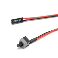
It is a simple ATX switch, it is connected to A2 and GND.
Youtube link:

ATx.jpg

I think maybe it should be related to Transceiver side(the code maybe), if I disconnect the hc-12 on Transceiver side the led (on the Receiver side) completely turns off. I think It transmits the sparkling signals. Even I have checked the other analogue in ports; A3-A5, the same result, the led sparkles, until holding the atx switch.

First thing, I do see a mistake in your TX code. GuideLaser is a value of 1 or 0 not a pin to digitalRead().

void loop() {
  xAxis = analogRead(A0); // Read Joysticks X-axis
  yAxis = analogRead(A1); // Read Joysticks Y-axis
  GuideLaser = digitalRead(GuideLaserbuttom);//Turning on/off the led laser

  Serial.write(xAxis / 4); // Dividing by 4 for converting from 0 - 1023 to 0 - 256, (1 byte) range
  Serial.write(yAxis / 4);
  //Serial.write(digitalRead(GuideLaser));
  Serial.write(GuideLaser);

  delay(30);
}

Does this change fix the turn off?

EDIT: Since you joystick values are transmitted and received properly, I do not think that the hardware serial issue discussed below is what is going on.

There may be an issue with HC12 running on the hardware serial pins on Nano's with CH340 usb/ttl driver chips.

https://forum.arduino.cc/index.php?topic=501282.0

You can try modify your code to use SoftwareSerial.

Dear Cattledog,

Thank you for the useful hint. You are right, no need for DigitalRead, but still there is a little issue, at this config, the sparkling of led light is solved, but it is on until you hold the ATX switch. I had changed the values of LOW/HIGH at both sides, this mode is the nearest for my goal. I think one solution is changing the switch I should use a switch with lock, which would be caused the switch to keep its state.

RX:
// ichi411-------_RX_-- RC - contorls two motor and a led laser

int x_pos;
int y_pos;
int  x = 0;
int  y = 0;

//Motor Pins
int EN_A = 11;      //Enable pin for first motor
int IN1 = 9;       //control pin for first motor
int IN2 = 8;       //control pin for first motor
int IN3 = 7;        //control pin for second motor
int IN4 = 6;        //control pin for second motor
int EN_B = 10;      //Enable pin for second motor
int motor_speed1;
int motor_speed2;

//GuideLaser
int GuideLaser;
int GuideLaserP=4;//control pin for GuideLaser


void setup ( ) {
 Serial.begin (9600); //Starting the serial communication at 9600 baud rate
 //Initializing the motor pins as output
 pinMode(EN_A, OUTPUT);
 pinMode(IN1, OUTPUT);  
 pinMode(IN2, OUTPUT);
 pinMode(IN3, OUTPUT);  
 pinMode(IN4, OUTPUT);
 pinMode(EN_B, OUTPUT);
 pinMode(GuideLaserP, OUTPUT);

                     
}

void loop () {
   x_pos = 510;
   y_pos = 510;
   

 while (Serial.available() == 0) {}
 x = Serial.read();
 delay(10);
 y = Serial.read();
 delay(10);
 GuideLaser= Serial.read();
 delay(10);


if (GuideLaser == LOW){digitalWrite(GuideLaserP, LOW);}////LED control part.
       else {digitalWrite(GuideLaserP, HIGH);}
 x_pos= x * 4;
 y_pos = y * 4;
  
if (x_pos < 400){     //Rotating the left motor in clockwise direction
   motor_speed1 = map(x_pos, 400, 0, 0, 255);   //Mapping the values to 0-255 to move the motor
   digitalWrite(IN1, LOW);
   digitalWrite(IN2, HIGH);
   analogWrite(EN_A, motor_speed1);
 }
 
else if (x_pos>400 && x_pos <600){  //Motors will not move when the joystick will be at center
   digitalWrite(IN1, LOW);
   digitalWrite(IN2, LOW);
 }
 
else if (x_pos > 600){    //Rotating the left motor in anticlockwise direction
   motor_speed1 = map(x_pos, 600, 1023, 0, 255);
   digitalWrite(IN1, HIGH);
   digitalWrite(IN2, LOW);
   analogWrite(EN_A, motor_speed1);
 }
  
if (y_pos < 400){         //Rotating the right motor in clockwise direction
   motor_speed2 = map(y_pos, 400, 0, 0, 255);
   digitalWrite(IN3, LOW);
   digitalWrite(IN4, HIGH);
   analogWrite(EN_B, motor_speed2);
 }

else if (y_pos>400 && y_pos <600){
   digitalWrite(IN3, LOW);
   digitalWrite(IN4, LOW);
 }
 
else if (y_pos > 600){        //Rotating the right motor in anticlockwise direction
   motor_speed2 = map(y_pos, 600, 1023, 0, 255);
   digitalWrite(IN3, HIGH);
   digitalWrite(IN4, LOW);
   analogWrite(EN_B, motor_speed2);
 }
 }
TX:

// ichi411-------_TX_-- RC - contorls two motor and a led laser

int xAxis, yAxis;
int GuideLaserbuttom  = A4;
int GuideLaser;

void setup() {
 Serial.begin(9600); 
 pinMode(GuideLaserbuttom,INPUT);
 digitalWrite(GuideLaserbuttom,HIGH);


}

void loop() {
 xAxis = analogRead(A0); // Read Joysticks X-axis
 yAxis = analogRead(A1); // Read Joysticks Y-axis
 GuideLaser = digitalRead(GuideLaserbuttom);//Turning on/off the led laser

 
 Serial.write(xAxis/4); // Dividing by 4 for converting from 0 - 1023 to 0 - 256, (1 byte) range
 Serial.write(yAxis/4);
 //Serial.write(digitalRead(GuideLaser));
 Serial.write(GuideLaser);


 delay(30);
}

Does it possible to fix it in which the led turns on when I hold the ATX switch not when I release the switch?

Please read How to Use this Forum and modify you last posting to post the code between the code tags created when you click on the </> button at the top left of the posting window.

You can change (modify)your last post is you use the "edit" or "modify" command seen at the bottom left of the post.

Regarding the issue you are facing, you will need to detect and transmit when the button "becomes pressed" rather than when the button "is pressed". You will need to change your code to detect when the button transitions from not pressed to pressed.

Please look at the ide example for examples>02.Digital>StateChangeDetection

One easy way to do this is to use the Bounce2 library. It is available through the library manager, and is a good and easy way to debounce and read buttons. Look at the Bounce2 library example "change". You can use the .fell() or .rose() command depending on how the button is wired.