Read analog (potentiometer) position and output 2 channel pwm for motorcontroller

Hello,
I have 2 actuators with analog potentiometer that I would like to drive parallel with the help of motorcontroller EM-339-PLI from Electromen.
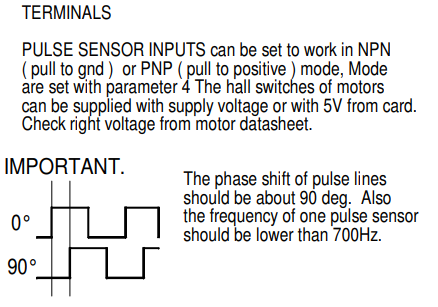
Problem is that the motorcontroller will not work with analog signals. It needs dual channel pwm signals that are phase shifted by 90 degrees, from each actuator.

I want to use an arduino to read the analog position signals (1 analog from each actuator) and output 2 dual channel pwm signals to my motorcontroller. 1 dual channel for 1 actuator.

Im a beginner when it comes to arduino and I only know basic C++. Before I spend too much time with this, I wish to know if this is even possible.

Picture from motorcontroller data sheet.
image

Thanks in advance.

Maybe something like this to start getting PWM from an analog input...

#define LEDPIN 3
#define POTPIN A0

void setup() {
  Serial.begin(115200);
  pinMode(LEDPIN, OUTPUT);
  pinMode(POTPIN, INPUT);
}

void loop() {
  int pwm =  map(analogRead(POTPIN), 0, 1023, 0, 255);
  digitalWrite(LEDPIN, pwm);
  if (pwm < 100) Serial.print(" ");
  if (pwm < 10) Serial.print(" ");
  Serial.print(pwm);
  for (int i = 0; i < pwm / 5; i++) { // plot the value
    Serial.print(" ");
  }
  Serial.println("*");
  delay(100);
}
1 Like

One key parameter is the <700Hz frequency, which means that the basic problem is that you have to switch a pin slower than every 1s/700/4=357us.

How is the potentiometer supposed affect the signals? Slow them down? As if it was the speed of a 0-700Hz signal?

I'd use the millis() math behind the Blink Without Delay example with micros() instead of millis() to trigger a 4-state state machine to toggle the pins. And I'd read the analog signal with something like the AnalogReadSerial example with stateChangeDetection to calculate the interval between state changes corresponding to 0-700Hz.

You're welcome in advance. Good Luck.

If I understand anything from description, I expect potentiometer to be position feedback from actuator?

Hi, @flexiit
Welcome to the forum.

Can you please post link to data/specs of actuators and EM-339-PLI?

Tom.. :smiley: :+1: :coffee: :australia:

1 Like

I really don't know. Can you read the "position feedback from acuator" or "analog (potentiometer) position" using @xfpd's code from #2?

As far as outputting a 2-channel signal based on what you read goes, it is unclear what you want the 2 channel PWM to do. Does it look like your pic and change frequencies proportionally to the position? Porportionally to an error in position? Does the pic Modulate Pulse Width (PWM?) based on the position? Should the motor turn both directions based on the signals? (like a quadrature signal into a stepper motor?)

An Uno can easily read a potentiometer position and output a 2-channel quadrature signal at well over 700Hz using micros(), digitalWrites and a state machine. It is completely unclear how you want to modulate the "2 channel PWM" based on the potentiometer.

This needs to be in the range of 0 - 1023. (I added a "graph" to the code in post#2).

I think you are right. Googling up the datasheet I see:


It looks like the signals are intended to be something like a quadrature position encoder signal from some Hall sensors.

If the 0-1023 potentiometer is supposed to map to a quadrature encoded position, that seems not at all to be PWM. You only get 1023 steps of resolution, and should likely (bidirectionally) slew the quadrature encoder signals towards the new position setting with some rate limiting.

Sounds possible, but the resolution seems terrible.

Here's a modification of your @xfpd's plotting code with some cycling through the intermediate encoder states:

#define LEDPIN 3
#define POTPIN A0

void setup() {
  Serial.begin(115200);
  pinMode(LEDPIN, OUTPUT);
  pinMode(POTPIN, INPUT);
}

int pwm, encoder;

void loop() {
  pwm =  map(analogRead(POTPIN), 0, 1023, 0, 255);
  digitalWrite(LEDPIN, pwm);
  doEncoder();
  // plot();
}

void doEncoder(void) {
  char states[] = "_/^\\";
  char gray[] = {0,1,3,2};
  static unsigned long last  = 0;
  const int interval = 20;
  if (millis() - last >= interval) {
    last += interval;
    if (pwm != encoder) {
      if (encoder < pwm) {
        ++encoder;
      } else {
        --encoder;
      }
//       Serial.print((encoder % 4)>>1, BIN); Serial.print((encoder % 2), BIN); Serial.print(' ');
//      Serial.print((gray[encoder % 4])>>1, BIN); Serial.print((gray[encoder % 4]&1), BIN); Serial.print(' ');

      // Serial.print(encoder % 4);
      Serial.print(states[encoder % 4]);
    }
  }
}

void plot(void) {
  static unsigned long last = 0;
  if (millis() - last >= 100) {
    last += 100;
    if (pwm < 100) Serial.print(" ");
    if (pwm < 10) Serial.print(" ");
    Serial.print(pwm);
    for (int i = 0; i < pwm / 5; i++) { // plot the value
      Serial.print(" ");
    }
    Serial.println("*");
  }
}

/^\_/^\_/^\_/^\_/^\_/^\_/^\_/^\_/^\_/^\_/^\_/^\_/^\_/^\_/^\_/^\_\^/_\^/_\^/_\^/_\^/_\^/_\^/_\^/_\^/_\^/_\^/_\^/_\^/_\^/_\^/_\^/_/^\_/^\_/^\_/^\_/^\_/_\^/_\^
1 Like

Nice job!
Anyway I feel that there is misunderstanding in sense that I'm not the author of the post.

Oops. Thanks. I edited it to properly credit @xfpd.

Here's a more fun plotting version of that toy

plot both encoder and pwm
#define LEDPIN 3
#define POTPIN A0

void setup() {
  Serial.begin(115200);
  pinMode(LEDPIN, OUTPUT);
  pinMode(POTPIN, INPUT);
}

int pwm, encoder;

void loop() {
  pwm =  map(analogRead(POTPIN), 0, 1023, 0, 255);
  digitalWrite(LEDPIN, pwm);
  doEncoder();
   plot2();
}

  char states[] = "_/^\\";
  char gray[] = {0,1,3,2};

void doEncoder(void) {
  static unsigned long last  = 0;
  const int interval = 20;
  if (millis() - last >= interval) {
    last += interval;
    if (pwm != encoder) {
      if (encoder < pwm) {
        ++encoder;
      } else {
        --encoder;
      }
//       Serial.print((encoder % 4)>>1, BIN); Serial.print((encoder % 2), BIN); Serial.print(' ');
//      Serial.print((gray[encoder % 4])>>1, BIN); Serial.print((gray[encoder % 4]&1), BIN); Serial.print(' ');

      // Serial.print(encoder % 4);
   //   Serial.print(states[encoder % 4]);
    }
  }
}

void plot(void) {
  static unsigned long last = 0;
  if (millis() - last >= 100) {
    last += 100;
    if (pwm < 100) Serial.print(" ");
    if (pwm < 10) Serial.print(" ");
    Serial.print(pwm);
    for (int i = 0; i < pwm / 5; i++) { // plot the value
      Serial.print(" ");
    }
    Serial.println("*");
  }
}

void plot2(void) {
  static unsigned long last = 0;
  static int lastEnc=-1, lastPwm = -1;
  if (millis() - last >= 100) {
    last += 100;
    int buflen = 81;
    char buff[buflen] ={0};
    for(int ii = 0; ii < buflen; ++ii){
      buff[ii]=' ';
    }
    buff[pwm/5]='*';
    buff[encoder/5]=encoder%4+'0';
    if(lastEnc != encoder || lastPwm != pwm){
      lastPwm=pwm ; lastEnc = encoder;
      Serial.println(buff);
    }
  }
}

Prints:

0                                                                                
1                                                                                
 2    *                                                                          
  3       *                                                                      
   0         *                                                                   
    1             *                                                              
     2            *                                                              
      3        *                                                                 
      2                                                                          
 *   1                                                                           
*   0                                                                            
*  3                                                                             
* 2                                                                              
*1                                                                               
0                                                                                
0                                                                                
 1       *                                                                       
  2             *                                                                
   3              *                                                              
    0             *                                                              
     1            *                                                              
      2           *                                                              
       3          *                                                              
        0         *                                                              
         1        *                                                              
          2       *                                                              
           3      *                                                              
            0     *                                                              
             1    *                                                              
              2   *                                                              
               3  *                                                              
                0 *                                                              
                 1*                                                              
                  2                                                              
                  2  *                                                           
                   3   *                                                         
                    0    *                                                       
                     1    *                                                      
                      2   *                                                      
                       3  *                                                      

Four analog input strip graph... : )

1 Like

Heh--Cool.

Leftover from a FORTRAN summer camp final project I have an old card deck which does biorhythm plotting by placing characters in a char buffer. (If I still had access to anything to read it and run it.)

It was old FORTRAN -- WATFOR. I'd also need one of these:

Mitxela did it. : )

This topic was automatically closed 180 days after the last reply. New replies are no longer allowed.