I tried to use a voltage sensor as seen in the video but when I measure something external it works fine but when I measure a pin pwm of arduino it can not do it
and I'm just trying to replace the analogue misleads found on the market with a digital
I tried to use a voltage sensor as seen in the video but when I measure something external it works fine but when I measure a pin pwm of arduino it can not do it
and I'm just trying to replace the analogue misleads found on the market with a digital
I'm sorry Delta_g I have difficulties with so much information that I need to assimilate, I try to understand everything but it is not always possible unfortunately in brazil we have little access to this, I'm just trying to fool the sensors of the car lambda, maf and map I thought that with pwm I could send a voltage and cheat the ecu, this is all for a project with hydrogen, can you give me a way for me to study instead of directing my studies on top of pwm?
Delta_G:
Exactly. Because it is PWM and not a stable voltage. I've been trying to explain that to you for a whole page. What part aren't you getting?If you want a stable voltage then you have to put a low pass filter on the PWM. That's the only way you'll read it as any voltage between 0 and 5V and have any hope of it being in any way close to accurate.
You have to stop trying to think of PWM as a voltage level.
What part of this am I not making clear?
First, I alway thought forums were happy places. "What part of this am I not making clear?" I am wrong. :-/
Second an easier way to get the voltage level is calculate it. analogRead(pin, 63); float voltage = 5*60/255; used as a float will be accurate enough.
Delta_G is right. PWM voltage is ideally a two level system ...... usually 0V levels and whatever the high level is...eg. 5V. Basically.... square waves are formed.
So, just like a multimeter being developed to read 'RMS' values of sinusoidal waveforms, an equivalent device would need to be used to measure time-averaged PWM .... that is, averaged over 1 period.
Running the pwm signal through a basic first order RC low-pass filter can do the filtering (or some kind of averaging) for us..... provided the time-constant of the filter is chosen appropriately. The arduino would then be able to capture (sample) the filtered waveform, which can then hopefully get close to the time-averaged value you're looking for.
On the other-hand, it would probably be better if you just calculate the time-averaged PWM voltage, rather than needing to tinker with some hardware to measure it.
Perhaps the easiest way would be to use a voltage divider to power the base of a npn transistor.
5v Collector
resistor1
---------------------Base
resistor2 /
ground Emitter
Then the voltage at the emitter would be 5v*(r1+r2)/r2
so a resistance of r1 5000 ohms and r2 5000 ohms would equal 2.5v
This could be used without an arduino.
When I wrote Reply #6 I thought the OP just wanted a number to display on an LCD - foolishly I thought the title was relevant ![]()
Now it is clear that what the OP really wants to do is create a varying voltage as input to an ECU. If the Arduino analogWrite() is used for that then (as has already been said several times) a smoothing circuit is essential. IMHO it would also be wise to check the effectiveness of the smoothing with an oscilloscope. A multimeter is next to useless for this situation.
As a completely different idea, I wonder if a digital potentiometer could be used to generate the varying voltage. I have not used a digipot so this may be a wacky suggestion.
...R
good morning everyone
I was looking at the digital potentiometer and I'm going to buy one for tests, I also thought if I change the pwm pin through an analog pin, can I do that reading? I tried to use a voltage meter and it works for external measurements but when I try to read the arduino pin it does not work does anyone know why?
rrsilver:
I also thought if I change the pwm pin through an analog pin, can I do that reading?
NO
...R
ok Delta_G I do not understand pwm, let's change the approach of the subject so that it will serve to finalize my project, let's say I want to read the voltage in any analogue pin of arduino, I get it just with code?
I will connect the car's lambda sensor to the arduino pin to send the voltage to the pin but this voltage has to vary, this will be done by the user who needs to see on the lcd screen the value he is sending to the O2 sensor, so I need to vary the voltage of the pin and show on my lcd as if it were a multimeter reading the value
rrsilver:
let's say I want to read the voltage in any analogue pin of arduino,
I think you are going off in the wrong direction but without knowing what you are thinking it is hard to point you in the correct direction so please tell us why you think you need to read a voltage?
If you read a voltage your Arduino will have a number between 0 and 1023. What do you propose to do with that number?
...R
rrsilver:
so I need to vary the voltage of the pin
You have been told probably a dozen times that an Arduino cannot vary the voltage on a pin - it can only make it 0v or 5v.
...R
ok Robin2 forgives me,
my knowledge of arduino is very small, I will continue my searches to find a solution that I can accomplish, thank you very much to everyone who gave their answers in this topic I was already very happy for your request
rrsilver:
ok Robin2 forgives me,
No apology is required.
However you have not responded to Reply #40 - and if you do we may be able to help.
...R
Robin2:
As a completely different idea, I wonder if a digital potentiometer could be used to generate the varying voltage. I have not used a digipot so this may be a wacky suggestion.
Sounds like a good idea. Or, as I think you mentioned before that.... if we know in advance the peak DC voltage for the PWM system (eg. 5V or 12V etc), then the LCD could just be made to output the estimated time-averaged DC voltage 'value'. Eg.... duty cycle 50% representing approx. 6V for a 12V PWM peak system. Like level 128 becomes (128/256) * 12V = 6V.
And level 255 becomes (255/256) * 12V = approximately 12V.
Good evening everyone
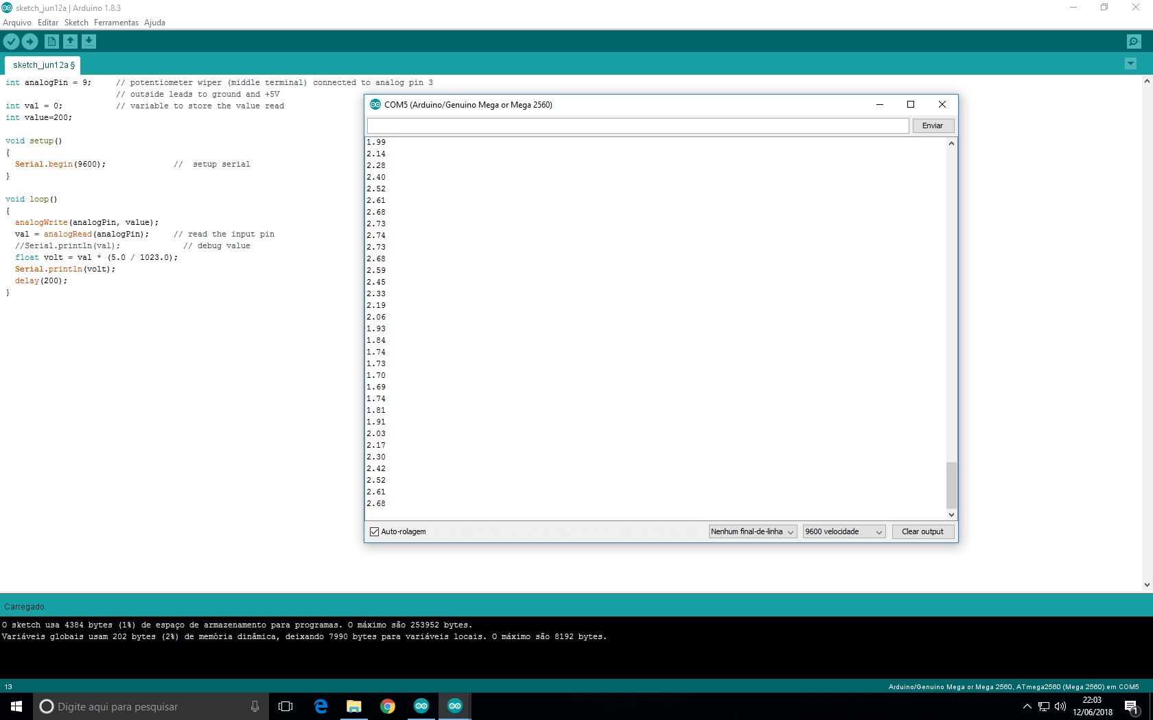
I got a new arduino I have here and I programmed it with little code and I did the test but the results are not exact in the serial port arduino as seen in the attached image, I just want to vary the voltage in some pin that gives to do this and show on a lcd screen, on the multimeter is showing at this time 3.84v
Have you actually read this thread ?
Using a PWM output does not vary the voltage. It will always be 0V or 5V. Only the duty cycle will change.
Did you read this before posting a programming question and if so why did you not follow the advice given about posting code and Serial monitor output ?
UKHeliBob:
Have you actually read this thread ?
Clearly not.
I give up.
...R
I already explained my fault with the title of the post and I apologized, I will explain what I need to do to solve this problem, I need in any pin of the Arduino less of the power supply of course, I need to vary the tension in this pin and show how if it were a multimeter but on an LCD, I only need the reading part of the pin because the communication with the LCD I have and it is great, so I will now summarize this question:
Vary the tension on a pin
read the tension value
I did tests on pin A0 and the values are random see the attached image please, ta on pin 9 but the same result was seen on pin A0
This is my last attempt.
thank you all.
How many times do you need to be told that writing a value to a PWM pin using analogWrite() does not change the voltage on that pin ? It changes the ratio of how long the pin is at 0V to how long it is at 5V
No matter how you read the voltage on that pin it will be at either 0V or 5V for most of the time and that includes reading it using analogRead(). It is possible that you might read the voltage during the short time that it takes to transition between 0V and 5V but that voltage is is not related to the value written to the pin using analogWrite()
In the code that you posted (wrongly by the way) you might just as well do the calculation of the average voltage on the pin based on the value written to it and not bother trying to read it from the pin.