Ok, I think I got it, you were telling me to use two modules to make a communication with those two for experimenting purpose, I think. I read and watched some videos and I think I understand now. I reread the bike manual and I see that the PCU (power control unit), that is the only system that reports a communication interface, communicates in CAN. The other ports don't specify what protocol they use but I suppose is still CAN.
Thank you for the datasheet. Now I have to buy a MCP2515 chip to use in combination with my Nano, then the chip will handle the CAN-H and L, so it's not a problem what voltage those 2 cables are carrying, correct?
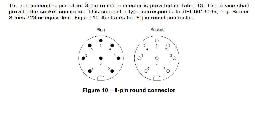
What I need is to get the pin 3 and 4 of the connector you posted, put them in che MCP2515 connected to the Nano and I can start the software part?
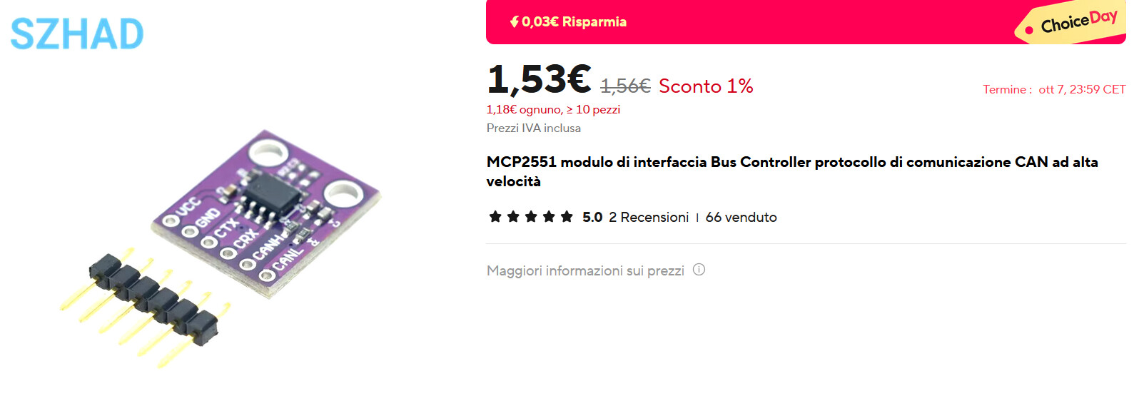
EDIT: My biggest concern now is that I watched many videos of people using only a MCP2515 module but others, like the one of the link I just posted, uses a combination of MCP2515 and a MCP2551 or MCP2562, or a specialized board altogheter.
Is a MCP2515 sufficient?
Those two modules have both the CAN controller and the physical layer interface. Simply add an Arduino, and they will work. Each module can both transmit and receive, so you only need one module to handle both functions.
I suggested setting up one module to transmit and one to receive in order to get your network working. When testing, make sure to have a few meters of wire in the bus. Additionally, the modules have a jumper plug near the bus interface that needs to be connected (jumped out).
CAN operates on a 60 Ohm bus. The jumpers place a 120 Ohm resistor across the bus, and you need one termination resistor at each end of the bus (I assume the bike has one at its end). This creates the required 60 Ohms of resistance. If you add any modules in between, be sure not to insert the termination plug for those intermediate modules.
May I ask you how do you know the transceiver is not necessary? I would like to know why.
I plan to take the CAN H and L from the OBD port, so I think there's no need to terminate the bus with the jumper, but I will take it into account if something's not working
Oh I think I got it, for "intermediate modules" you meant other modules apart from the one I'm trying to connect? So I don't have to put the terminal resistance in those module, but only on the first one. Given that I want to place only one module, I have to place that, correct?
CAN does not specify types of connectors or pinouts. The connector I show is from the CANOpen recommendations. If the E-bike manufacturer followed the CANOpen recommendations then it should work. I suggest you check voltages and signal levels on the pins before you connect anything.
First you need to find out which pin is ground and which is CAN ground.
However, Im not sure how you might go about doing that and I don't want to tell you to do something that may damage your bike.
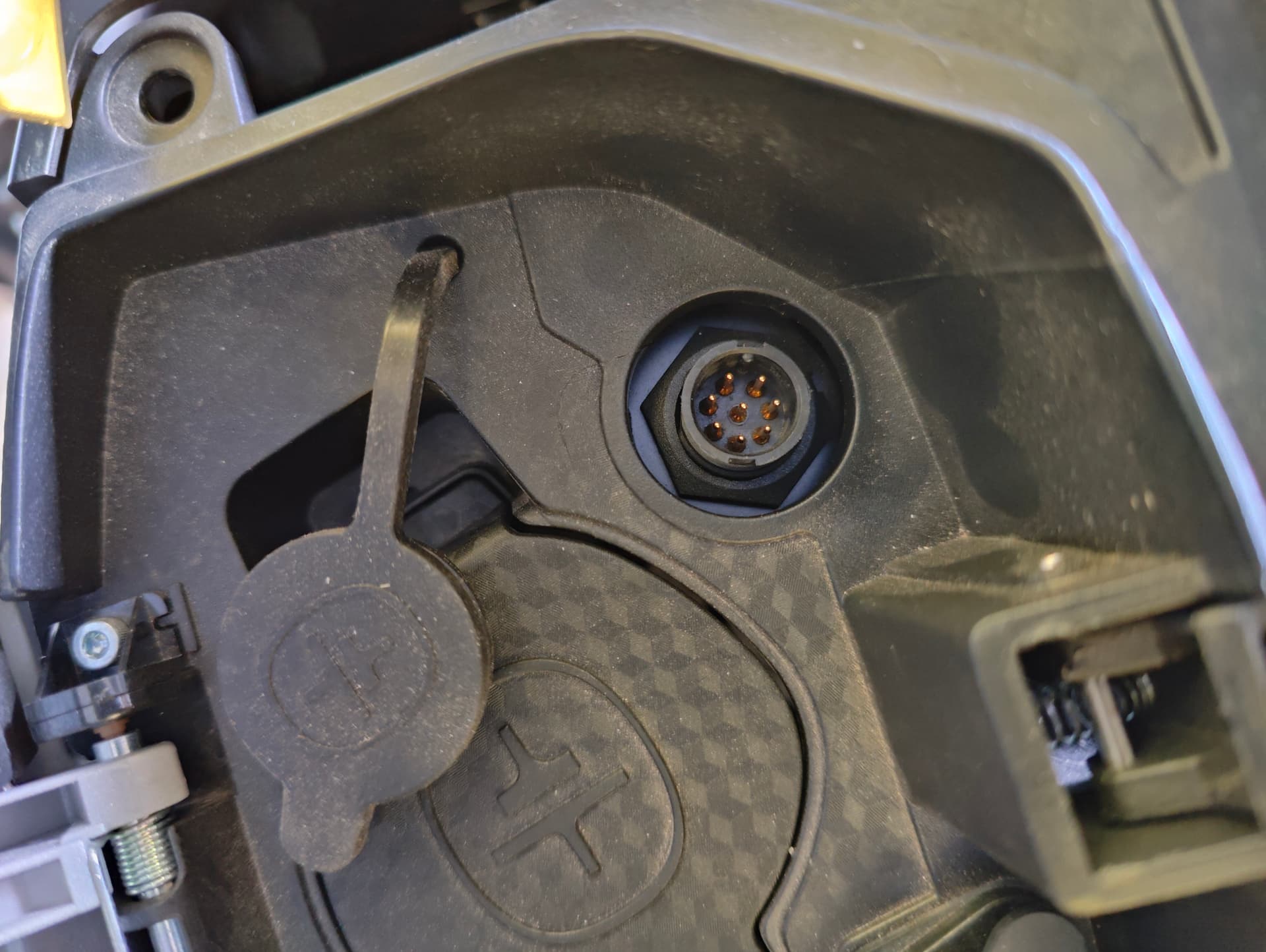
May I ask you where did you find this diagram? I finally make it to test with my tester my diagnostic port and the pins don't seem to match, given that the power comes from different pins and other pins returns some values that change with time that I think can be the CAN H and L but I would like to do some research before I try to connect to arduino.
I also found some other resources but everything is about a 5 pins CAN port, not 8
I found the correct pinout. I can confirm because I was able to read CAN frames with an Arduino and a MCP2515 module, now I will have to find a CAN sniffer software to filter and identify them, thanks to all for the help.
Pinout here in case the image goes missing:
4: CAN_L
5: CAN_H
6: 12V
7: GND