TL,DR: I want to read the Serial data that an electric motorcycle sends to its screen through a 4 pins cable with an Arduino Nano and no shield. Is it possible? Can someone guide me?
Hello. For my project I would like to read the data sent by my electric motorcycle, an Ovaobike MCR-S, with my Arduino Nano and have it react in some ways, like reading the battery, reading the press of buttons, activate features etc, that are not the scope of this topic.
I read many topics but they are all about reading the CAN bus with some shield while I want to read the data the bike sends through a 4 pins cable (that's why I think it's Serial) to its LCD screen. Given that every possible information I want is displayed on the screen I prefer to read that Serial instead of getting a cumbersome shield.
My plan is to make a Y cable, one end to the screen and the other to the Arduino, so that I can power it up when the bike starts from the 12v (through a buck converter set to 5v) and the ground, then read the two remaining cables through Serial.
Before I buy cables and connector I would like to know if it's possible / if my plan makes sense and if someone is kind enough to guide me in this project.
4 pins doesn't mean it's serial rx tx. Why not I2C?
Anyway, if you don't know the protocol, what communication data means, it can be difficult to decode it.
I assumed it was serial because the screen it's not composed of pixels, instead it has some predisposition to light certain predesigned parts. Still I could very possibly be wrong, what other standards could it be? Is it possible to know it with trial and error?
I2C LCD displays are quite common. Some custom segment display maybe.
You can observe if there are some labels next to the pins. What driver chip that display is using etc.
But don't think it will be something like "connect to serial monitor and it's printing the speed and battery level".
The pins have no label and I can't open the screen that is encapsulated in a block with no visible openings and the manual does not show how to open it, nor does it report how the screen works.
I was expecting to connect through the serial and read a bunch of strings and numbers that I would then interpret by pressing buttons and recognizing the patterns.
There are few doubts. It's not guaranteed that 12V line is designed to supply extra power that buck+arduino needs. And IF the signals are also 12V, you need to convert them down to 5V as well.
If I had to take a guess, I’d say it’s likely CAN, with power on the other two wires. However, you need to post the make, model, and series of the motorcycle for a more accurate answer. Yes, you’re correct that it’s serial if it’s CAN, but there are many different serial protocols. You need to identify the specific protocol so you can decode it properly. Typically, we define the protocol and its format before designing the hardware.
If that's not sufficient I can plug to another soure. Either way, as said, I plan to use a buck converter to decrease to 5v.
Unfortunately it's an almost unknown brand. As said, it's an Ovaobike MCR-S, and that's about it. I have a service manual that I can upload, but that does not say how the internal communication happens.
No, but the bike has either 144v for the motor or 12v for everything else as per the manual. Also I measured with a tester and it's 12V.
Buck converter doesn't help you with the data lines. You need different type of converter for that aka level shifter.
Anyway you wrote you measured 12V. On what wires?
I measured on a power supply cable for USB charger, but given that everything on the bike is either 144 or 12, as per manual, I suppose it's 12v.
Still, if even the data is 12v, that I didn't thought of, that could be a problem. If I still have to get another piece of hardware, might as well be the CAN shield at this point.
Do you know if that could be of more easy reading?
Obviously you should measure the voltage on those display wires if that's the connector you need to use. Find GND and measure voltage between that and other 3 wires.
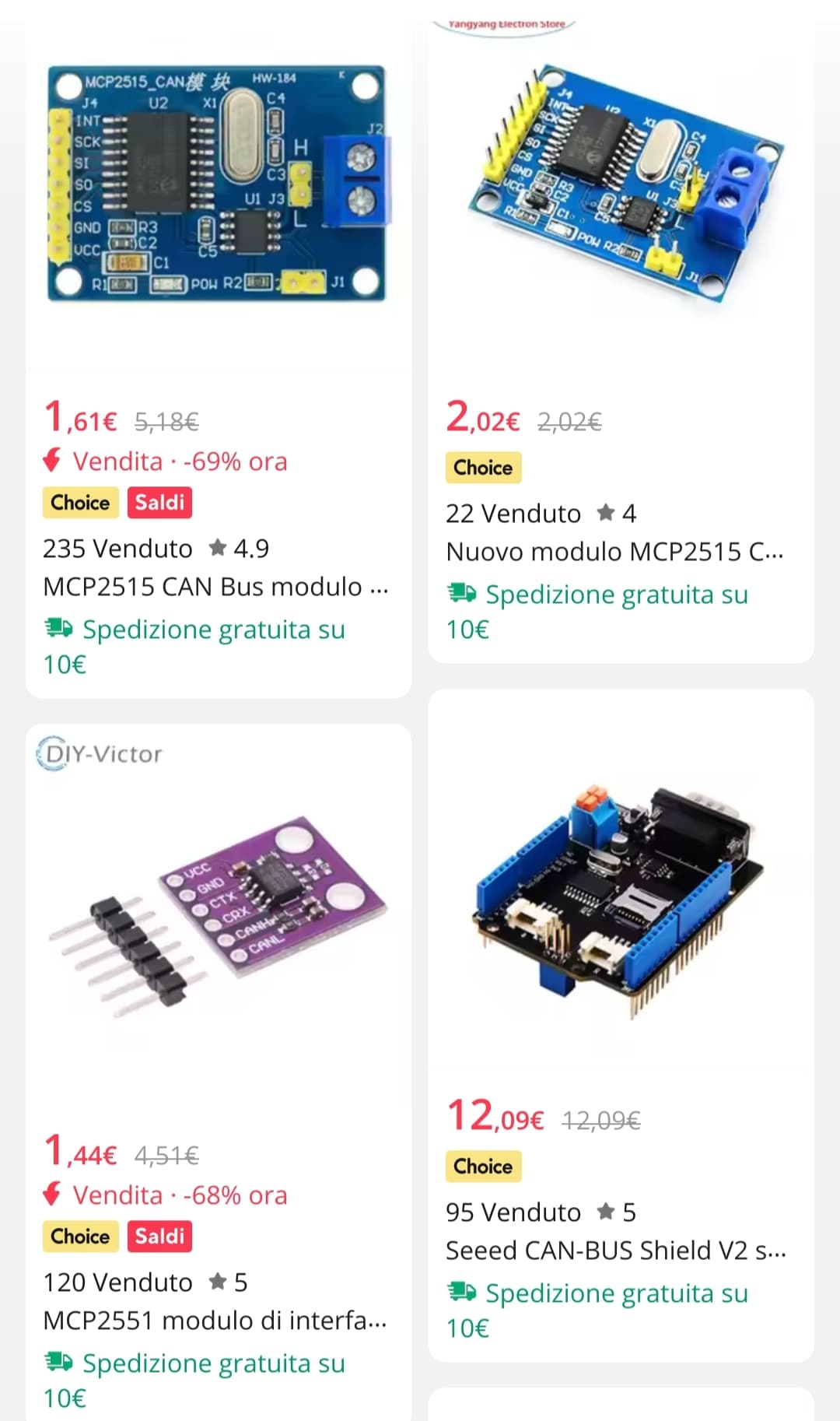
Also I saw some CAN chips on china's best known store that area like 2€ or less and are not so big as I thought, implying that those are the ones I need
All four boards seem to have the CAN physical layer chip. The board in the lower left won’t work unless there is a controller managing it. The other three boards (though I'm not certain about the lower righe one) are MCP2515 modules, which work very well as they include both the MCP2515 controller chip and the physical layer interface.
Cory Fowler wrote the mcp_can library, which works great for these modules. He also provides both receive and send examples. Start by building two modules—one for sending and one for receiving—and get them working. Also, keep in mind that CAN transmissions must be acknowledged by another module on the bus for communication to be successful.
There are various types of CAN in use, including single-wire and differential. They operate similarly, but the interface is different. The bus must support both dominant and recessive modes. For single-wire CAN, think of an open-collector transistor driving the bus with a pull-up resistor. You can have multiple devices connected, within reason. The two-wire differential mode bus is the original and most commonly supported version.
I recommend reaching out to the manufacturer for specific information about the bus and the protocol they are using. Before connecting anything, use a voltmeter to ensure everything is within the appropriate range (5V or less).
Let's see if I got it.
I need two MCP2515 chips like the upper two in the image I posted earlier. I connect both to my Nano and both chips to my OBD and I use one to read, the other to send to the CAN bus, but to do it the OBD to which I connect the chips must carry 5v.
Given that I am sure it carries 12v, what can I do?
I am reading this Instructables that links to a sparkfun shield that has both MCP2515 and a MCP2551, don't I need the MCP 2551 too?