Hi,
I'm powering Arduino Nano from this powerbank. The powerbank requires one button click to turn on and two clicks to tuwn off. I want to emulate the double click with Arduino, so that it requires one click to turn on and off.
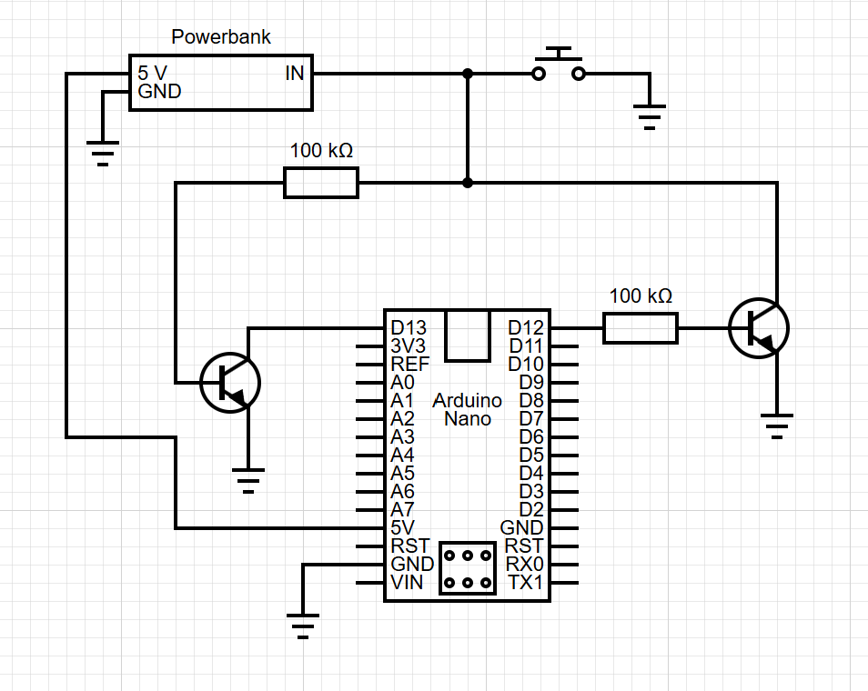
My initial idea was to read voltage (using for example pin D13) on the IN pin (with internal pull-up) of powerbank, and when it switches from high to low, and back to high I would set the D13 Arduino pin to low and back to high to emulate the second click. See diagram below:
Problem here is back powering of the D13 pin. I thus split the reading and writing to two pins. I used this method for protecting the reading pin (see left part of diagram below).
The IN pin is 3.7 V when the power bank is off and 5 V when of. So Arduino should have no problem reading that. Thare is internal pull-up on the pin, so it can be grounded if I bring common ground to arduino GND. I tested the circuit without transistors and it worked. I'm just afraid of what might happen if I turn of the Arduino.
I would suggest a relay, they make nice button replacements. To do it electronically I would like to see a schematic of the circuit I am interfacing to.
I can't see a reason for that to not work OK, but you should build it and check the voltages around the circuit in each of its possible states very carefully, and look for signs of phantom powering and other things that are not as you expect.
The 100k on D12 is too high for a transistor working as a switch, and you dont know (you could measure) the current that passes when the button is pressed. I’d suggest using a logic level compatible mosfet instead.
You can lose the transistor on D13, the 100k resisitor will itself provide enough protection.
Thank you for your suggestions. I tried to build the circuit and measure the voltages. The is around 15 mV on D13 when the Arduino is off. I think I will lower the 100 kOhm resistor going to the NPN or switch the NPN for MOSFET. I'm not sure about the solution with only resitors because that will probably drain the powerbank a little more.
The base emitter junction of the transistor is a forward biased diode - so with 5V and 0.7V across BE you have 0.043 ma continuous.
(not sure if measuring from “IN” is valid")
The input resistance of a digital pin configured as an INPUT (not INPUT_PULLUP) is very high so your current would be MUCH less without the transistor.