pwillard:
The Pins on the Arduino are for "signals". These Signals are used in digital logic to state that the pin is on logic level state "1" or logic level state "0".
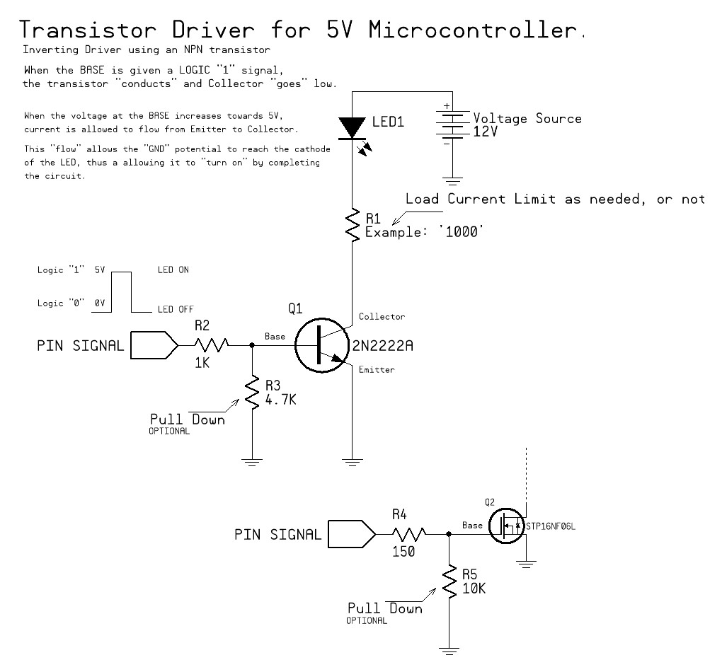
To turn these signals into peripheral device controllers, we need a few things. 1) we need to know how much current your peripheral device will draw 2) we need some muscle (already mentioned... get some NPN transistors) 3) we need some control over signal currents (get some resistors)
Item 1 means, find your devices data sheet (IE; LED's specifications and look at how much current it needs.)
Item 2 means, if the load wants less than 400 mA, you can use most "common" small signal transistors. IEl 2N2222A If it needs more than that, then you need to start searching for a "power" transistor (engineers usually reach for a logic level mosfet at this point) It doesn't hurt to order some STP16NF06L from Digikey at this point anyway.
Item 3 means, protect your parts. If you use a npn style transistor like 2N2222A, you want a value like 1000 ohms between the pin and the base pin on the transistor. If you use a Mosfet, to protect you from "yourself", add a 150 ohm resistor from the pin to the gate and a 10,000 Ohm resistor from the gate to GND.
See drawing (yeah, I know I called the gate a "base", sue me)
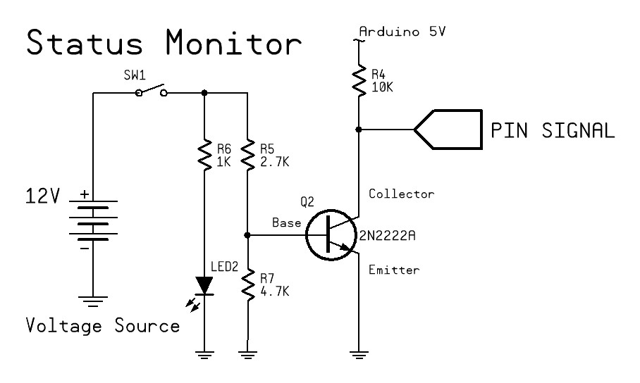
Appreciate your time in explaining that to me as well as including the image. It has really helped a lot. However, I'm using the pin to detect weather the switch (which would be in series with the diode) is open or closed.
Paul__B:
Hang on! I am saying that you need to tell us what you really want to do. I am saying that the resistance of the wire (if it is only the other side of the room) is not the problem. the question is - what sort of LED do you want to use; for what current is it rated? Then we can tell you whether it is practical to use the 5V from the Arduino or whether it is critically necessary to connect to the 12V as you originally described.
And as usual, exactly what do you want to do and why? What is the purpose of the exercise anyway?
The Pull Down in pwillard's FET circuit is not optional, but should be on the left hand side of R4.
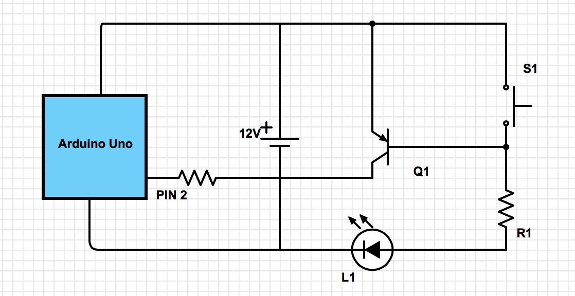
I think I am making this ALOT more complicated than it is, so Ill try explain it again.
I have a switch which is located on the other side of the room where the arduino is located. This switch is used to arm/disarm a room security system and it has a LED (which has a 20mA max limit) in series with the key switch to show if the switch is open or closed.
However, since its about 1.5 meters away from the arduino I assume this is too far for it to power the LED + provide enough voltage back to the pin to give it a digital HIGH or LOW value.
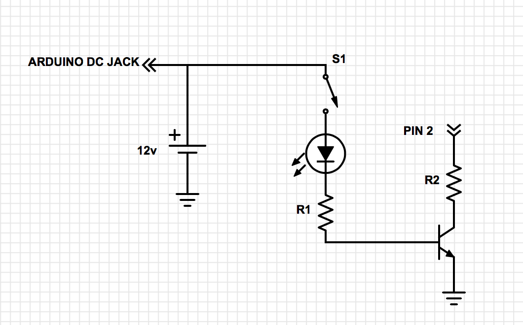
I tried creating another schematic (below) which might explain it better.
(BTW, the reason its a 12v source was because that was the voltage supplied by the power source I was using to power the arduino (its what I had laying around). The switch isn't powered by a separate power supply, just not powered by the arduinos 5v reg)
EDIT: I only realised now that I forgot the pull up resistor on pin 2 in the diagram