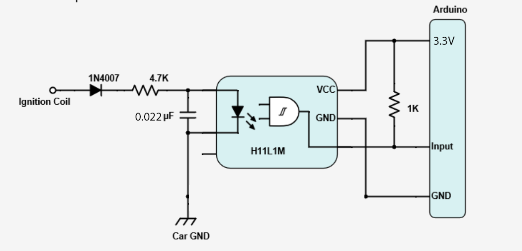
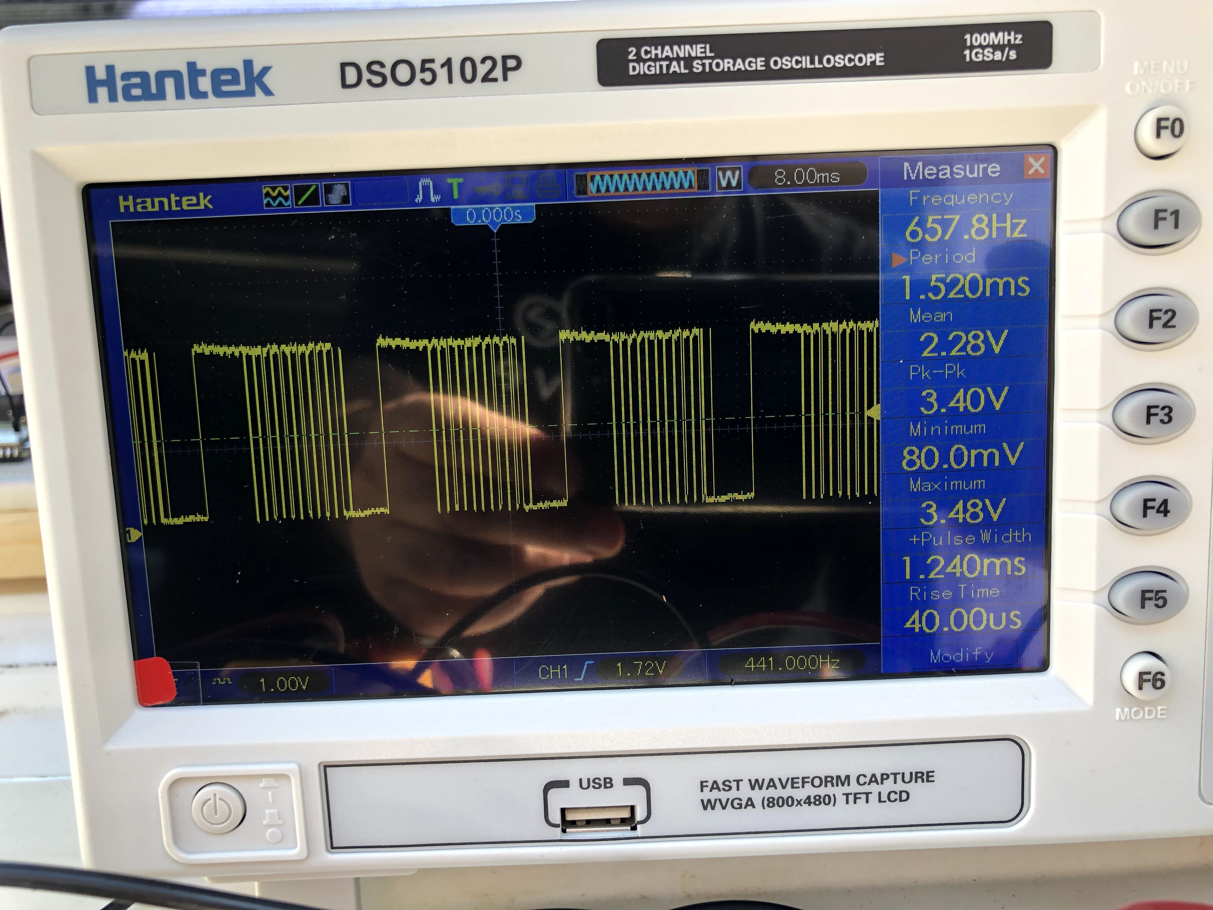
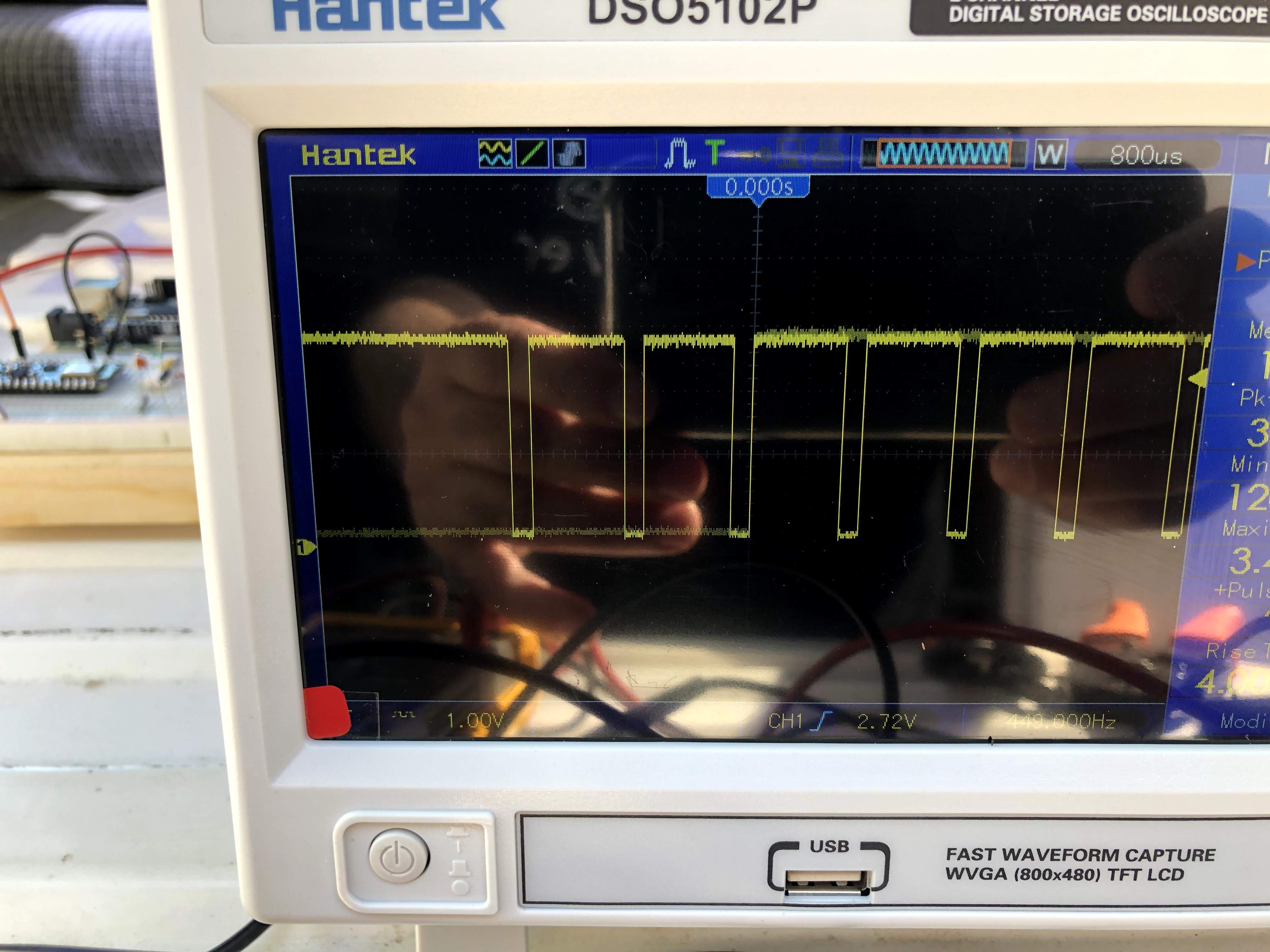
I am trying to read the pulses of the coil and calculate the RPM on an old (86) Vanagon. I found a few topics about simular projects and tried to learn from them. I am using Arduino NANO 33 BLE for the project and the circuit I build for it is based on an H11L1M (Schmitt Trigger Output Optocoupler). Please see attached schematics of the circuit. I am getting very clean pulses on the output side (see attached photo) but I am not sure I am reading the correct information as the frequency is not changing when I am raving the engine. It stays the same. Any thought on what can it be? The last photo (sorry about the reflections) is how the input signal looks like. The software I developed read an average of 40 pulses per 100 ms using interrupt.
Here is the code. The code works fine when I am generating square signal with another Arduino board.
const int hallPin = 3;
volatile int rpmcount = 0;
int hallState = 0;
int lasthallState = 0;
int rpm = 0;

void setup() {
  Serial.begin(9600);
  pinMode(hallPin, INPUT);
}

void loop() {
  hallState = digitalRead(hallPin); //Reads current hall state

  if (hallState != lasthallState) { //if current hall state is different than last hall state then:
    if (hallState == HIGH) { //check if current hall state is HIGH, if yes then:

      rpmcount = 0; // set number of interrupts to 0, to begin counting

      attachInterrupt(digitalPinToInterrupt(hallPin), rpm_fan, FALLING)
      delay(200); //wait 100ms, it will run rpm_fan during that time and count LOWs on pin 3

      detachInterrupt(digitalPinToInterrupt(hallPin)); //detach interrupt for calculating

      rpm = rpmcount * 5; // convert to Hz
      Serial.print(rpm)
      Serial.println();
    }
    delay(13);
  }
  lasthallState = hallState;

}


void rpm_fan() { /* this code will be executed every time the interrupt 0 (pin2) gets low.*/
  rpmcount++;
}