Hello,
I was just looking for some advice on reading data from a sensor.
Generally I have worked with I2C sensors, though for this specific application this sensor is required. Here is the Datasheet.
Am I under thinking this by assuming I can connect this directly to the Arduino 5v power supply? Do I need a differential supply or is 0-5v okay?
I'm reading lots of mixed things about whether I need op amps or whether I am able to power and read this directly.
The datasheet only shows the Wheatstone bridge, without electronics.
To use this sensor, you must add a stable excitation voltage for the bridge, a differential amplifier, and a high-resolution A/D.
Fortunately this is all available on a common/cheap HX711 breakout board.
Leo..
Hi Leo,
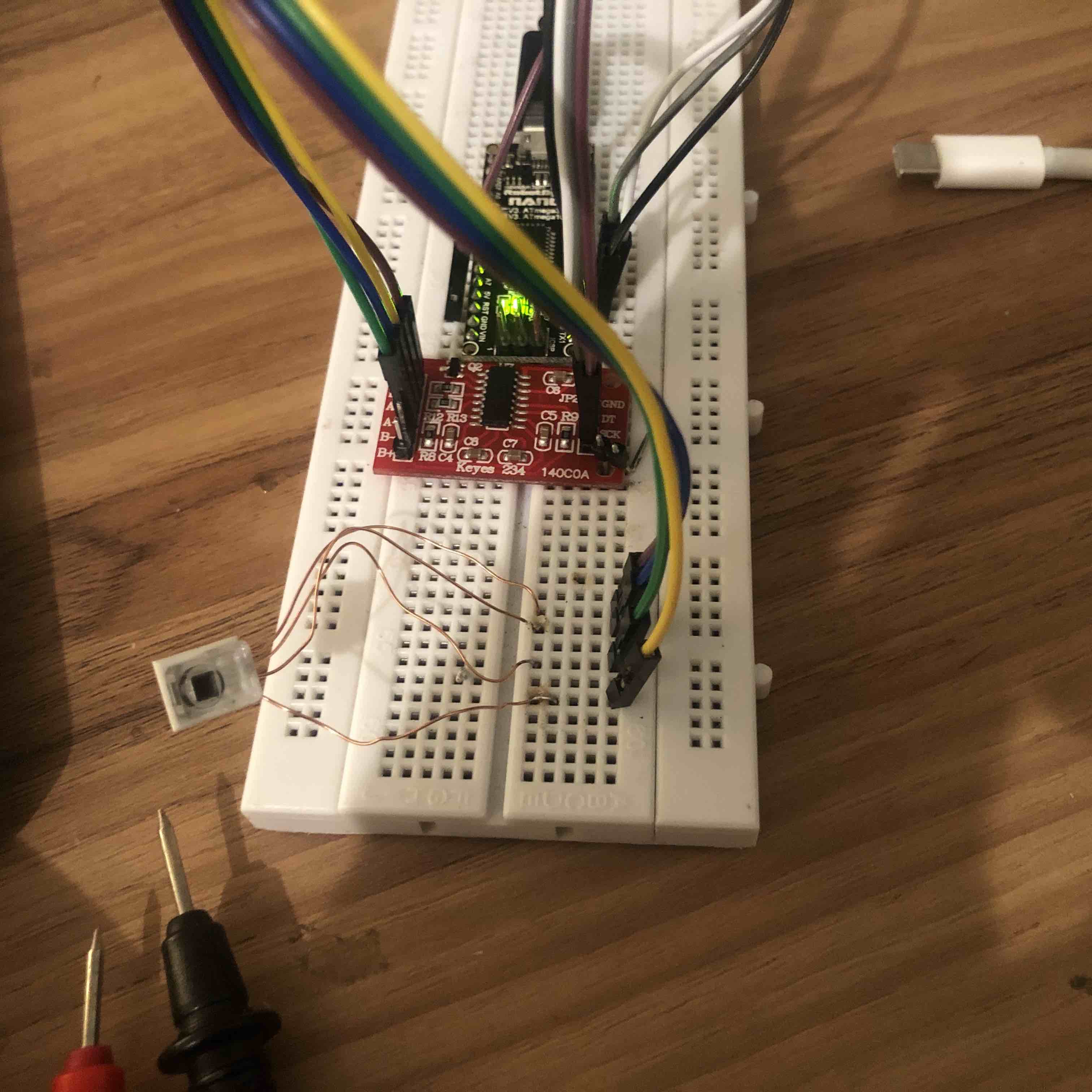
I purchased the HX711 breakout (Bought it from a local supplier and turns out its actually a Keyes 234 140C0A) - but appears to be almost identical.
I've tried using the Bogde library and having some issues with the readings.
No matter which gain I set (Channel A 128, Channel A 64, Channel B 32), my readings are returned as:
HX711 reading: 8388607
I can't see many spots I could mess up in the wiring:
Please read the "how to post" guide of the forum.
We need all the details to help you.
Code, pictures, which Arduino, etc.
Start by measuring the voltages on the sensor.
There should be about 4.25volt on E+
The two A inputs should be about half of that, with very little voltage (<20mV) between them.
Leo..
E+ must be ~4.25volt, and E_ must be 0volt (ground), otherwise there could be a wiring/connection problem.
Did you properly solder the pins to the HX711 module?
Leo..
Not sure what you mean.
There must be ~4.25volt across E+ and E-
But E- is directly connected via the HX711 module to Arduino ground.
There should be 0volt on E-
Leo..
When I check the continuity between E- and GND, there is a connection. When I check the voltage between E- (GND, on the HX711, or the metal casing), it remains around 0.7v.
There is 4.25V across E+/E-, though E- is not 0V.
Any suggestions on the next step I should take?
A few things you may wish to try and or consider. Your HX 711 module should look like this. Also this is the data sheet for your sensor. Using an Arduino rather than mess with the Excitation Voltage of the HX 711 module If I measure the 5 Volt pin of my Uno or Mega boards I get a very stable 4.97 volts when the boards are externally powered using a 9.0 volt supply. Obviously if you are relying on USB to power your board your mileage will vary.
Your sensot relies on an excitation voltage of 1 to 10 VDC (Calibrated at 6.0 VDC). Your sensor sensitivity is uV/V/mmHg and your range is -30 to 300 mm Hg (-0.58 to 5.8 PSIG). That tells you pretty much what your output should be for a given excitation voltage at a given pressure. Likely here, the most important thing is your excitation voltage must be stable. I would use your Arduino board 5.0 volt out to supply your HX 711 and your sensor excitation.
While this example code and samples applies to load cells you may want to at least look at the code with a focus on the Calibration code and the Scale Output code. The main difference between what you are looking to do and the linked code is the units of measure.
Anyway this is just an optioon if you continue to have problems. Also Your board ground pins should be tied to your HX 711 ground and your excitation negative of your bridge. All a common bond.
The HX711 ground><Nano ground wire needs investigation.
My Nano definitely has the USB socket grounded to the Nano ground pin.
Check all continuity with a DMM.
@Ron.
Powering the sensor from 5volt is unwise.
You loose ratiometric relationship between the A/D of the HX711 if you do, leading to instability.
Leo..
Wawa:
The HX711 ground><Nano ground wire needs investigation.
My Nano definitely has the USB socket grounded to the Nano ground pin.
Check all continuity with a DMM.
I swapped to using a different MEGA2560, so the issue above is fixed.
I have ordered a new HX711 (The proper SparkFun breakout).
I'll post back with any changes - the 0.7v E- just doesn't seem right, and nothing I can determine the source of so far.
Cheers,
Oliver
Wawa:
The HX711 ground><Nano ground wire needs investigation.
My Nano definitely has the USB socket grounded to the Nano ground pin.
Check all continuity with a DMM.
@Ron.
Powering the sensor from 5volt is unwise.
You loose ratiometric relationship between the A/D of the HX711 if you do, leading to instability.
Leo..
Thanks Leo, so your saying use the HX711 module excitation correct?
Yes, E+ excitation is regulated (powered from the potentially dirty 5volt supply),
and the HX711 uses the same E+ excitation voltage for it's internal 24-bit A/D.
Ratiometric, so it the 4.25volt increases, sensor output increases, and A/D sensitivity decrease with the same amount. Keeping A/D result the same.
Leo..