I was trying to debug a HX711 to see if it is functioning correctly. I wired 4 resistors in a wheatstone bridge config to the sensor, and was expecting readings of around 0 when printing on the uart terminal, but I get almost random values, ranging from -100 to 17000, back to 0 and -5000!
Is this a normal behaviour of the sensor? I don<t have asecond one to test, and I am wondering if there are specific API calls from the library that could change the reading behaviour of the sensor. Thanks!
thanks for the reply. I tried with 1k resistors that I handpicked with same values read on my multimeter. Still, the values have that weird behavior where they slowly drift, i.e. increase until they reach 32k, then jump to about -32k, and start increasing again, or decrease, etc.
I tried playing around with the calibration factor, but it doesn't have any effect.
Wawa:
That's not a picture of the setup, and I hope you didn't connect E+ to to a potentially unstable VCC.
The VCC I was using for the bridge was the 5V pin on the arduino. Maybe it isnt stable enough? I also tried hooking up the bridge with the same configuration, but while removing the GND and VCC connections (thus leaving only A+/- and E+/-) I get stable -1 values (meaning it could not read correctly I believe), but why is that? Aren't E+ and E- enough to create a voltage potential between A+ and A-?
Wawa:
The HX711 has it's own regulated/stable 4.25volt excitation output (E+), derived from Arduino's 5volt supply.
Use that to power the bridge.
Leo..
When I power the bridge with E+, (like on the attached image below) I Seem to get no reading. The serial monitor prints the same value as fast as it can, compared to when I plug E+ to VCC, the values print slower and vary. Is this normal?
thanks for the reply. I tried with 1k resistors that I handpicked with same values read on my multimeter. Still, the values have that weird behavior where they slowly drift, i.e. increase until they reach 32k, then jump to about -32k, and start increasing again, or decrease, etc.
If they aren't 0.01% resistors on a temperature-stable heatsink yes they will drift, resistor values are not
constant due to temperature changes caused by self-heating.
Actual strain guages are thermally bonded to each other and well heat-sinked, temperature drift is much
less (still an issue though).
Remember you are performing measurements with this kind of setup to ppm levels of precision...
Wawa:
Connecting the bridge to E+ E- A+ A- is the only way.
Still no picture of the setup.
Leo..
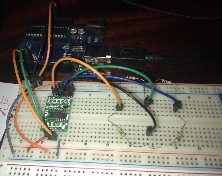
Here, I took a picture of the setup attached below. I still get the readings stuck at 13108 when using this config, are you able to tell if there is an error in the setup?
Thanks for your great help.
MarkT:
If they aren't 0.01% resistors on a temperature-stable heatsink yes they will drift, resistor values are not
constant due to temperature changes caused by self-heating.
Actual strain guages are thermally bonded to each other and well heat-sinked, temperature drift is much
less (still an issue though).
Remember you are performing measurements with this kind of setup to ppm levels of precision...
This is true, I will switch to strain gauges once I understand why I get those messy readings with resistors. I just can't find an explaination online to why I get those readings stuck at 13108 when I do not connect my E+ to 5v on the uno and E- to GND.
Here is code again, in case:
#include <Arduino.h>
#include <SPI.h>
#include <Wire.h>

#include <HX711.h>

HX711 scale;

#define LOADCELL_DOUT_PIN 5
#define LOADCELL_SCK_PIN 6

#define CALIB_FACTOR -200

void setup()
{
  // put your setup code here, to run once:
  Serial.begin(9600);
  scale.begin(LOADCELL_DOUT_PIN, LOADCELL_SCK_PIN);
  scale.tare();
  scale.set_scale(CALIB_FACTOR);
}

void loop()
{
  // put your main code here, to run repeatedly:

  int scaleReading = scale.get_value(10);
  Serial.print("read: ");
  Serial.println(scaleReading);
}
On the green HX711 module GND is not connected to Arduino GND directly but via an input protection diode and so E- is not 0V (measured to Arduino GND) but about 0.6V. I don't remember what is E+.
So sorry! The image on next post (it failed to upload on this one)
Wawa:
While waiting for your image...
E+ should be 4.25volt, E- should be 0volt.
A+ and A- should both be 2.125volt, and there should not be more than 10mV between them
(with DMM pins on A+ and A-).
Leo..
This is interesting, I have 2,7V on all 4 pins (A+/- and E+/-) with this current setup. Do you think of a reason why? I have checked continuity between the 4 pins and none of them is.
Wawa:
Wiring seems ok, apart from too much solder on the pins of the module.
Remove all the wires. and move the module to another position on the breadboard (BB do have bad contacts).
Then only connect VCC/GND to 5volt/GND of the Arduino, and measure E+ with black lead of the DMM on the metal shield of the USB socked (GND).
It should be 4.25volt..... ±0.1volt.
If not, check/re-solder, or try a new HX711 board.
Leo..
Thanks, I measured 0V from E+ to GND, and made sure the 5V was reaching VCC of the HX711 module. I am wondering if it might be a setting that deactivates the E+/- pins sent to the chip (maybe it would be saved on its eeprom?) I am not the first person who used this specific module and I am unaware of any changes that could have been made firmware wise. I cant find anything on the datasheet though..
You could be right.
The chip has a power-down mode, activated with the clock pin.
Not sure if that will also affect the E+ excitation supply.
Haven't got a board handy at the moment, so I have to pass that problem on to another forum member.
Leo..