I like simracing and got tired of my terrible g29 pedals. I have a very... precarious understanding of electronics and programming, but somehow I managed to piece up a code on an arduino leonardo to turn it into a generic controller, so I can build a new set of pedals with it. Point is, the brake is supposed to use a loadcell instead of a hall sensor. I managed to insert the hx711 scale library into it, and it worked. I changed the sample rate to 80hz instead of the factory 10hz with a soldering trick I saw on youtube. And managed to get a normal reading on my loadcell with it. Problem is, I live in a third world country (Brasil) and these things gets expensive fast. I bought a 20kg loadcell just to test it, as a 40kg one was literally 5 times more expensive (or even more). And I realized that what I'm using to assemble the pedal is literally an aluminum bar (although it's not a solid bar, it's hollow).
So, I decided to buy strain gauges instead and turn the pedal itself into a loadcell. But here comes the problem: I built a half bridge with 2 gauges on opposing sides, but when I wire it to the hx711 I get a stable reading (either 7014 or 6955, just to exemplify). And as I am new to these things still, I didn't bother to even get a multimeter, so I deduced some or both gauges must have a bad connection. So I decided to build a full wheatstone bridge with some resistors and replace one with which gauge to test if they are working. And to my dismay, the full bridge got the same readings (either 7014 or 6955). And I realized I could literally pluck up to 2 resistors and the reading kept the same. I then just plugged E+ directly into E- and A- into A+ and got the same reading. Adding a resistor didn't change anything. I then plugged the loadcell back in and it worked just fine, so it's definitely not a connection or board issue. This is driving me absolutely insane. I built the bridge exactly as I saw people doing on youtube, and following the diagrams. The fact that it gets the same reading no matter what I do boggles me, and even scouring the internet I couldn't find anything or anyone talking about this problem. When E+, E-, A- and A+ are unplugged, it reads around -500 with noise. But when I plug it into anything that connects these poles it gets this weird static reading that doesn't change no matter what I do. So, point is: how should I build a wheatstone bridge in a breadboard, and how should I connect it to the hx711? Can someone make an illustration of how it should look like in a breadboard, and in a way that any dummy like me could understand?
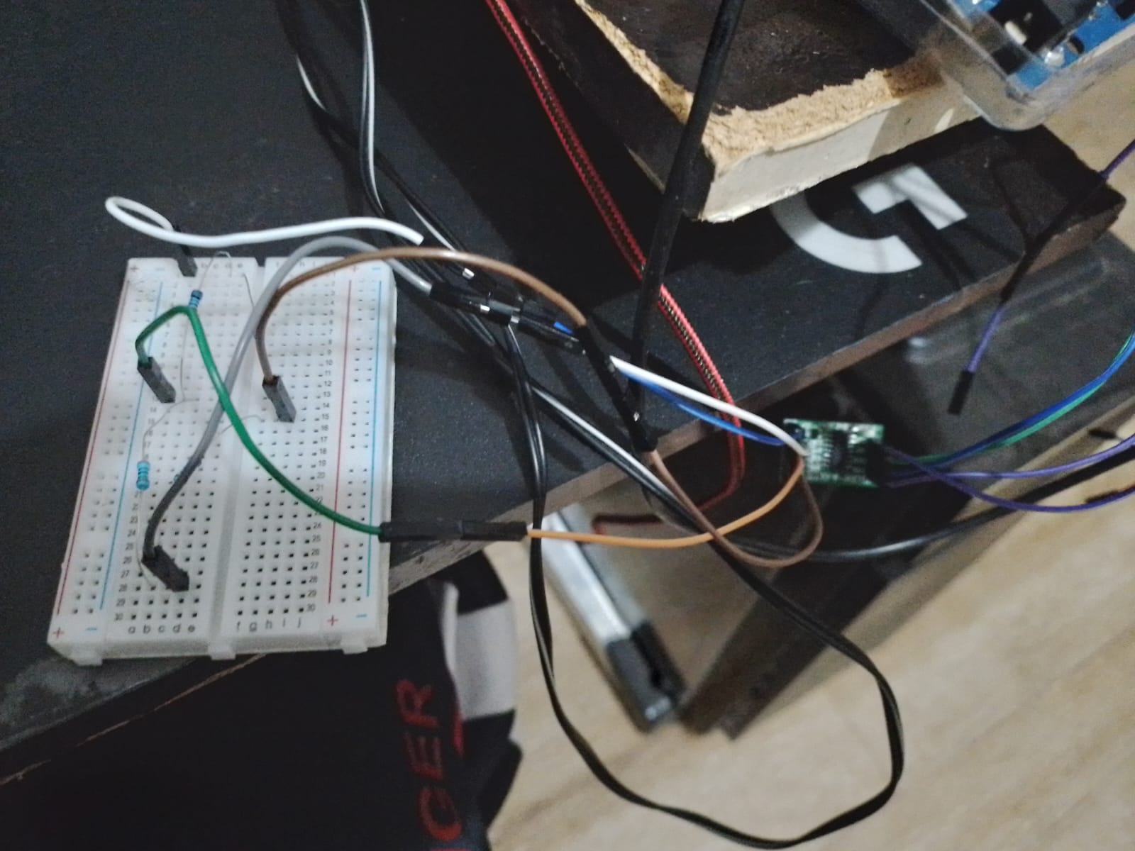
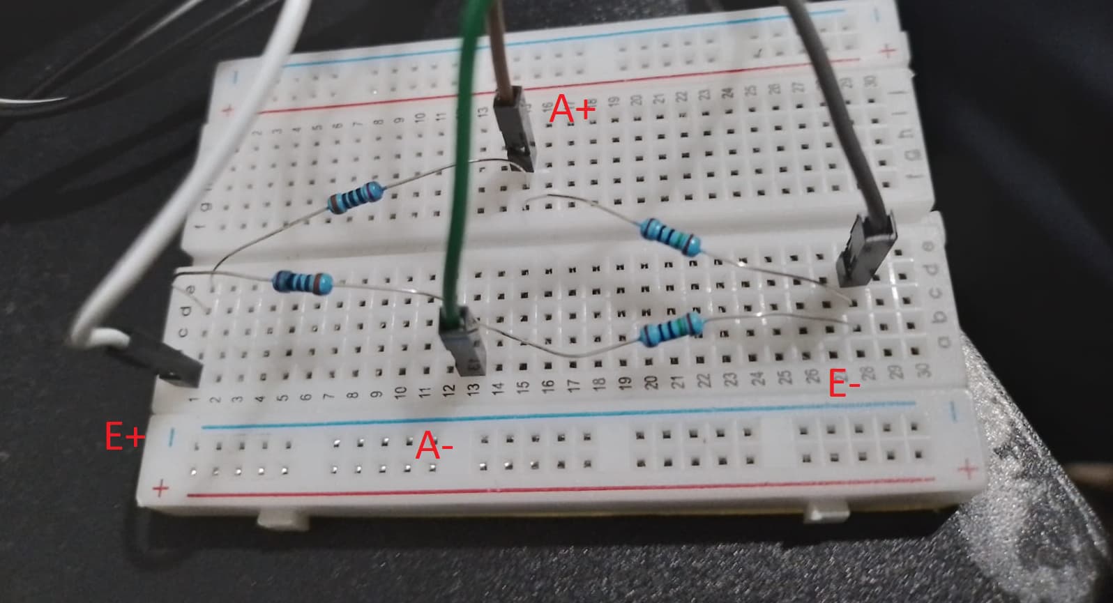
There is a single, 20kg loadcell, and it works normally when I wire it onto the hx711. So, I tried my best, here are the photos I managed to make (my phone is terrible, sorry):
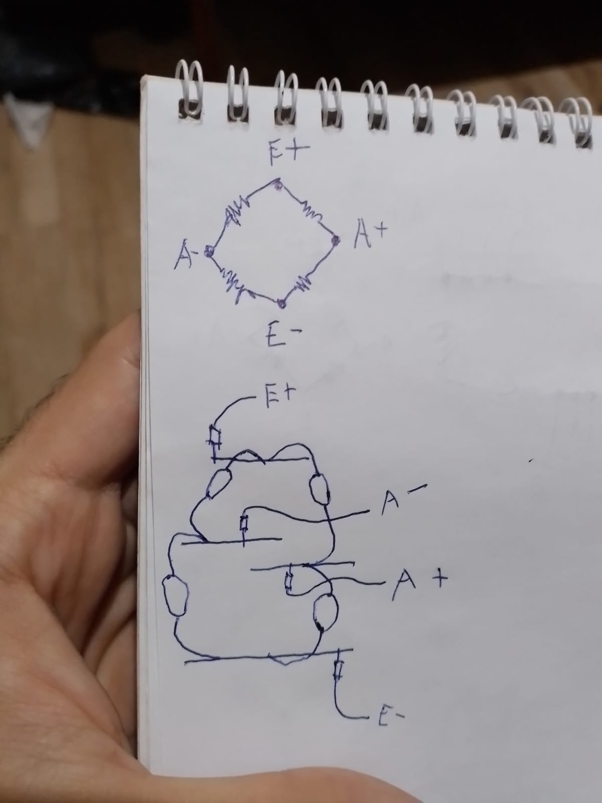
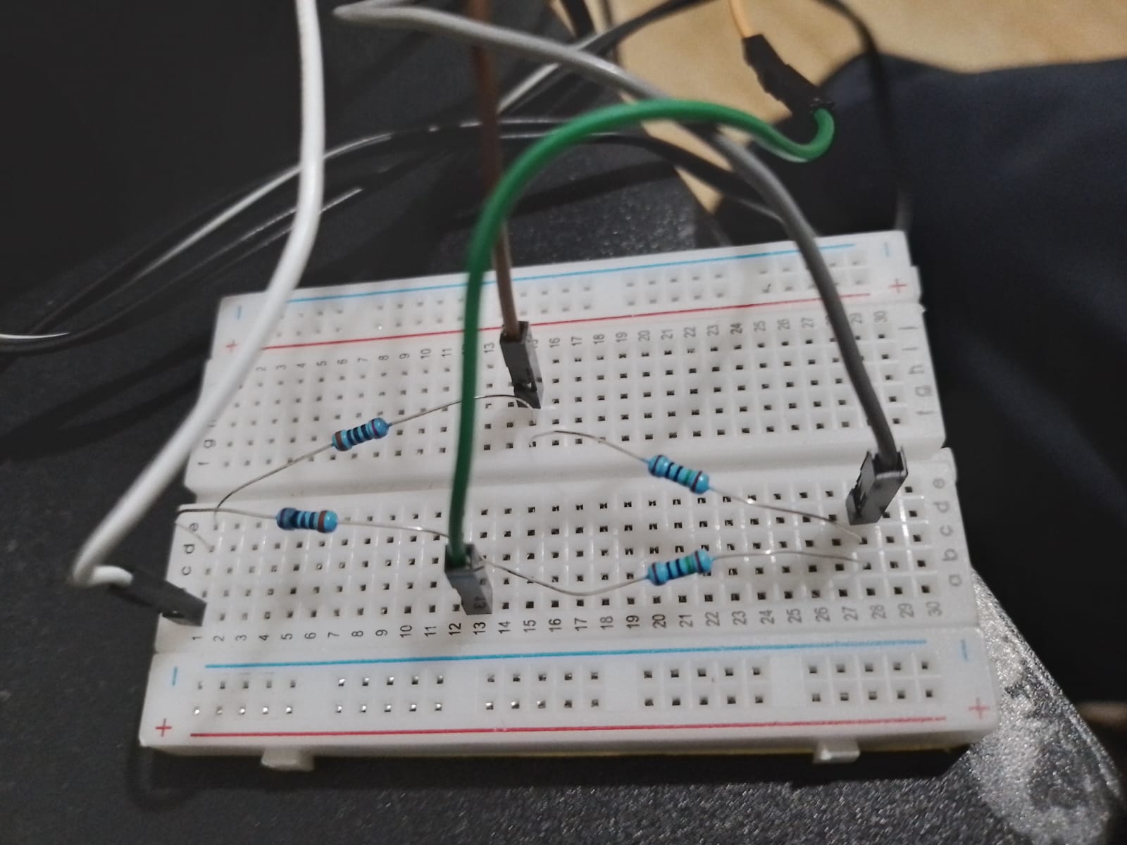
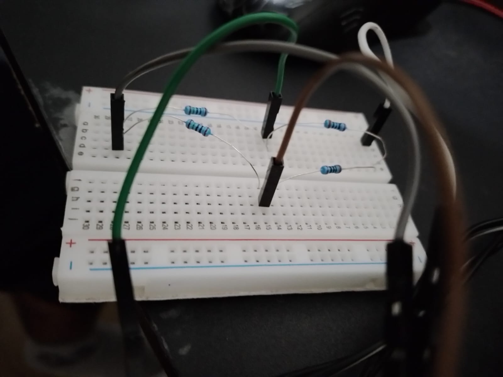
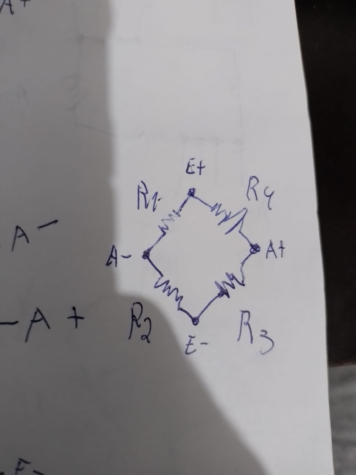
The schematic I tried to follow, and how I wired it into the breadboard:
So, it works like this: when the hx711 isn't wired to anything, it gets a noisy reading around -550. When I wire it into the loadcell, it reads around 0 with little noise, and the signal varies when you try to bend it, positively by pressing one side, negatively in the other direction. When I plugged the shown circuit into it, it reads a static 6955. If I remove both R1 and R3, it keeps reading 6955. If I take any of the others, it goes back to around -550 with noise (the "open reading"). If I just plug E+ into E- directly and leave A- and A+ disconnected, I get the same 6955. If I had a multimeter, I could test the circuit and wiring. But by "shorting" E+ and E- through each connection and seeing if it would return 6955 I could test if it is the wiring, and it's not, it's running normally. I can't test each resistor's resistance, though, neither the circuit's tension in each point. But considering everything is connected properly, is this schematic/circuit wired correctly? Or am I mistaking anything?
First off NEVER ever rewire the circuit while it is powered up, if you have been doing stop it.
Now as one bridge works but two do not, comes as no surprise.
The output from the bridge is wired up to the Arduino and allows the analogue input to work correctly. But when you wire two bridges up, you in effect, short the output signal from the second bridge to the same ground as you are using from the first bridge. This, to use a technical phrase, "screws things up right royally".
You need to look at isolating the two bridges so the output you are trying to read have a common ground. This is probably best done using operational amplifiers.
P.S.
Still waiting for
and a full schematic that shows all of your wiring, not just bits of it.
Sorry, I don't know how to do that... I have a pretty precarious understanding of how electronics work yet, and I know that it sounds dumb but I legitimately don't know what would be "a sketch that gives up these bad results" and " a full schematic that shows all of your wiring, not just bits of it"
But anyway! Later yesterday night I used the tried and true method of F*ing around and finding out, and I indeed found out. I think people will be mad with me, but since I opened this topic I have to close it out, and I think it may be of help to other people in the future (maybe). The problem was simply that I was mixing 150 and 200 ohms resistors. I used two each, and wanted to build the bridge unbalanced so I could measure the output on the serial monitor, and then balance it to see how the signal changes, and if it is working. I thought that 50 ohms of difference were a small value but it isn't, apparently. I did exactly what you told me NOT to do (sorry, I didn't know lol) and tried a lot of different configurations with the board running, and tried a lot of combinations of just shorting E+, E-, A+ and A- in different orders to test the outcomes. To my luck, the hx711 module I use has effective anti-idiocy contigency methods, so I wasn't able to fry it. But I came with some hipothesis. Before I explore them, let me say that the bridge I built, exactly the same way I showed earlier but this time with all resistors with the same resistance, gave an output around 3300 (not that it matters much, arbitrary value) and that fluctuated a bit, probably in part due to noise and in part due to the 1% tolerance of the resistors, I guess. Removing any resistor resulted in either the static 6955 signal or the noisy -550. What I learnt by testing different ways of "shorting" the pins is that this signal (that sometimes was 7014, it changed randomly) must be some kind of anti-surge mechanism or something like that that simply "closes" the circuit internally, that's probably why it is triggered when some of the pins receives a value that must bee over a certain limit and why it is completely static, with no noise. Using different resistors probably launched the values at A+ and A- beyond a certain limit and then the board becomes unresponsive, that's my guess. One of the aspects that drove me insane was that nothing influenced this value, it completely ignored resistance. One of the tests I did was shorting E+ and E-, and then plugging them on a resistor. And I realized that over the resistor, instead of locking into 6955 I would get the open reading, -550 with noise. Which means that the resistance probably reduced the current/tension/whatever enough not to trigger the 6955 mechanism (which I guess is some kind of anti-surge or anti-short, as I mentioned). That's why I was getting completely illogical results and why it made 0 sense, even more considering that the readings when I plugged the loadcell where absolutely normal and functional. But anyway, I'll get a multimeter, a new set of strain gauges and try again when they arrive some weeks or a month from now. With the multimeter, I'll be able to test the gauges (they didn't work with the bridge, so I probably wired them badly) and I realized that it's not only necessary to have 4 to close a full bridge and get the most signal, it is also cheaper than using precision resistors to build a half bridge for only 2 gauges, so I'll try it. Maybe I'll post it here if it works, or if it doesn't, but anyway, thanks for the attention and help! I hope this serves someone eventually.
that is 30% difference, depends to program settings max voltage between +A and - A is 80 mV, so with 30% resistors difference you are over that, use all resistors the same (the same colors marks on all resistors) then connect parallel to one of the resistors 100k resistor and observe the changes.
Removing one of the bridge resistors it is causing unbalance of it and voltage on +A, -A is 5V.
1. Prepare hand-made wheatstone bridge as per Fig-1 by twisting the equal-valued (I have used 1k) arm resistors. The bridge does not work on breadboard.
Connect VCC of HX711 Module with 5V of UNO
Connect GND of HX711 Module with GND  of UNO
Connect DT of HX71 Module with A1 of UNO
Connect SCK of HX711 Module with A0 of UNO
Connect E+ of HX711 Module with Right Node of WS Bridge.
Connect E- of HX711 Module with Left Node of WS Bridge
Connect A+ of HX711 Module with Bottom Node of WS Bridge
Connect A- of HX711 Module with Top Node of WS Bridge
3. Power up the UNO.
4. Use a DVM and measure voltage across E+ and E- at the WS ridge side. The reading should be around 3.4V.
5. Use DVM in mv scale and measure voltage across A+ and A- at the WS Bridge side. The reading is about 2.4 mV (theoretically it should be zero, but is not zero due to tolerance variations in the arm resistors). If you get -ve reading, then swap the A+ and A- at the HX711 Module side.
6. Upload the following sketch which measures the counts proportional to the input voltage. The avaerage counts should be around: 3379839 (looks too high). Check with your actual Load Cell for the amount of mV it generates when the rated load (say: 20 kg) is applied on it.
/* This program takes 10 samples from LC + HX711B at
   1-sec interval and then computes the average.
*/

unsigned long x = 0, y = 0;
unsigned long dataArray[10];
int j = 0;

void setup()
{
  Serial.begin(9600);
  pinMode(A1, INPUT); //data line  //Yellow cable in my Setup
  pinMode(A0, OUTPUT);  //SCK line  //Orange cable in my Set up
}

void loop()
{

  for (int j = 0; j < 10; j++)
  {
    digitalWrite(A0, LOW);//SCK is made LL
    while (digitalRead(A1) != LOW) //wait until Data Line goes LOW
      ;
    {
      for (int i = 0; i < 24; i++)  //read 24-bit data from HX711
      {
        clk();      //generate CLK pulse to get MSB-it at A1-pin
        bitWrite(x, 0, digitalRead(A1));
        x = x << 1;
      }
      clk();  //25th pulse
      Serial.println(x, DEC);
      y = x;
      x = 0;
      delay(1000);
    }
    dataArray[j] = y;
  }

  Serial.println("===averaging process=========");
  unsigned long C1 = 0;   //C1 = Count-1 against no fuel in the Tank

  for (j = 0; j < 10; j++)
  {
    C1 += dataArray[j];
  }
  Serial.print("Average Count = ");
  C1 = C1 / 10;
  Serial.println(C1, DEC);
}

void clk()
{
  digitalWrite(A0, HIGH);
  delayMicroseconds(50);
  digitalWrite(A0, LOW);
}
7. Short A+ and A- at the WS Bridge side. Check that the count is around: 8771 (makes sense).
8. The HX711 Module is fine as it is responding to the change in the input signal.
That is because you are tackling a subject way way outside your compensated level.
So far you have just shown bits of your wiring, like endless drawings of bridges. You have not shown how these have been wired up to your Arduino.
Your code, is something that you have written on your machine that shows the results you are complaining are wrong. You have never posted ALL that code.
No you come up with some cock and bull explanation of how you fixed it.
Don't bet on this.
Anyone following this is never going to know how to reproduce what you did.