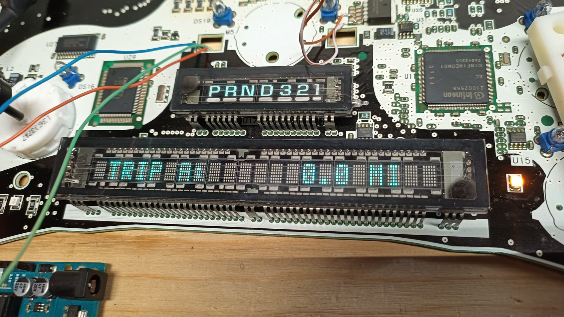
Hello all, I'm looking to intercept serial data sent to a custom display chip that controls a 1x22 VFD. It has 3 lines:
-Latch
-Clock
-Data
All idle high at 5V. The incoming data appears to be at about 1Mhz, in two bursts per display update (I can't tell how much data per burst due to the limitations of my scope.)
I already have the data wires in place into SPI pins on the Arduino, but I don't know much about receiving serial data.
I copied this code from Gammon.au, modified the data rate, and added the SPI mode line:
// Written by Nick Gammon
// February 2011


#include <SPI.h>

char buf [100];
volatile byte pos;
volatile boolean process_it;

void setup (void)
{
  Serial.begin 250000);   // changed by me - for 1Mhz data

  // turn on SPI in slave mode
  SPCR |= bit (SPE);

  // have to send on master in, *slave out*
  pinMode(MISO, OUTPUT);

  // get ready for an interrupt
  pos = 0;   // buffer empty
  process_it = false;

  // now turn on interrupts
  SPI.attachInterrupt();
SPI.setDataMode (SPI_MODE2);  //added by me
}  // end of setup


// SPI interrupt routine
ISR (SPI_STC_vect)
{
byte c = SPDR;  // grab byte from SPI Data Register

  // add to buffer if room
  if (pos < (sizeof (buf) - 1))
    buf [pos++] = c;

  // example: newline means time to process buffer
  if (c == '\n')
    process_it = true;

}  // end of interrupt routine SPI_STC_vect

// main loop - wait for flag set in interrupt routine
void loop (void)
{
  if (process_it)
    {
    buf [pos] = 0;
    Serial.println (buf);
    pos = 0;
    process_it = false;
    }  // end of flag set

}  // end of loop
I'm using PuTTY to monitor the serial since the Arduino serial monitor data rate is limited. I get a few random characters every 4th display update or so, but that's about it.
The problem is, I don't really know much about SPI, what I'm doing, or how the data is stored and pushed out to PuTTY.
Once I can reliably store the display update "bursts", I can then move on to processing the data (I have a character map from the display chip datasheet).
Can anyone help with the data capture portion? What other info do I need?
Thanks all!
I guess I should clarify: I don't exactly know what is being captured & stored by the Arduino with the above code, or how to reliably monitor that. I just get a few random characters out of the serial monitor. Which is a start, I guess.
It sounds to me like the protocol is binary (which is what I would expect). The sketch is assuming the data is printable text. Try this version. It will gather bytes until there is a half-second gap (up to 1000 bytes) and then dump them in hexadecimal.
#include <SPI.h>

volatile char V_buf[1000];
volatile unsigned V_pos = 0;
volatile unsigned long V_LastArrivalTime;

void setup(void)
{
  Serial.begin(250000);   // changed by me - for 1Mhz data

  // turn on SPI in slave mode
  SPCR |= bit(SPE);

  // have to send on master in, *slave out*
  pinMode(MISO, OUTPUT);

  // get ready for an interrupt
  V_pos = 0;  // buffer empty

  // now turn on interrupts
  SPI.attachInterrupt();
  SPI.setDataMode(SPI_MODE2);  //added by me
}  // end of setup


// SPI interrupt routine
ISR(SPI_STC_vect)
{
  V_LastArrivalTime = micros();
  // add to buffer if room
  if (V_pos < (sizeof V_buf) - 1)
    V_buf[V_pos++] = SPDR;
}  // end of interrupt routine SPI_STC_vect

// main loop - wait for flag set in interrupt routine
void loop(void)
{
  noInterrupts();
  if (V_pos == 0)
  {
    interrupts();
    return;  // No data
  }
  unsigned localPos = V_pos;
  unsigned long localLastArrivalTime = V_LastArrivalTime;
  interrupts();

  if (micros() - localLastArrivalTime > 500000ul)  // Half a second
  {
    // Input has paused so let's dump the buffer
    for (unsigned i = 0; i < localPos; i++)
    {
      if (V_buf[i] < 0x10)
        Serial.print('0');
      Serial.print(V_buf[i], HEX);
      Serial.print(' ');
      if ((i % 16) == 15)
        Serial.println();
    }
    noInterrupts();
    V_pos = 0; // Start over at the beginning of the buffer
    interrupts();
  }

}  // end of loop
Awesome, that appears to work! I suspected that I had some data type problems.
Here's an example of the output for this screen:
(there's a button that scrolls between messages)
Reverse-engineering a protocol tends to be easier if you have multiple different messages. That way you can look for commonalities and differences. For example, I would collect the odometer message again after moving a mile.
I can cycle through 4 different messages. So far I can't make any sense of the data vs. the character map, but I'll keep poking at it.
Processing the data into characters is going to be another challenge.
Thanks!
It's possible the data the Arduino is receiving is inverted (meaning every 1 should be a 0 and every 0 should be a 1) or that the bits in every byte are sent MSB first or LSB first (meaning the first bit of each byte received is either bit 0 or bit 7).
(I'm not allowed to upload attachments yet)
I don't know if this is the exact datasheet, but I can't find one for the actual OKI L9203-2. I'm assuming the protocols and character map are the same, but I could be wrong.
That binary doesn't match that hex. If you don't display the binary correctly you are going to have a hard time making sense of the data. I'd rather work in HEX.
You would expect these two messages to be almost identical but the binary is looking very different for the first half of the message: TRIP A: 0100 10000010 100101 0101 1000001 010 010 010 0110 0110 1011001 010 01000 101010 10010010 0100 1011100 0100 0100 0100 1110100 0100 10010010 0100 TRIP B: 01001 0100 1001010 01010 1000010 0100 0100 0100 01100 01100 10110010 0100 01000 101010 10010010 0100 1011100 0100 0100 0100 1110100 0100 10010010 0100
Understood about Hex vs. Binary. I was changing this:
Serial.print(V_buf[i], HEX);
Serial.print(V_buf[i], BIN);
Just to compare the outputs. The character map shows the the MSB and LSB of each character as binary, so I thought I'd see if anything looked familiar on first glance.
So I'm seeing the "82" byte change to "42" which is a good sign (only difference in the display is A character vs. B character). If my conversion is correct:
A = 1000 0010
B = 1000 101
The character map shows (MSB, LSB)
A = 0011 0001
B = 0011 0010
So the bit moves, but I still have some deciphering to do. I wonder if building a new HEX character table would make the process simpler?