I see a square pulse - that's the Arduino's signal?
What to do next.... check your wiring, very carefully and thoroughly, as I suspect there's something wrong. A solder bridge or so, maybe a part that's connected wrong - something at least.
The schematic that I designed should keep the gate voltage (referenced to GND) to about 0-12V. The voltage you report are too high for your MOSFET: most can handle no more than +/- 25-30V on the gate, referenced to the source pin. More than that will kill a MOSFET.
Actually without the MOSFET in place you should be able to see the VGS pulses. That should be the output of the two optocouplers. Back in #101 you reported some good values for that. Make sure that hasn't changed - it's what you provide to the gate that counts.
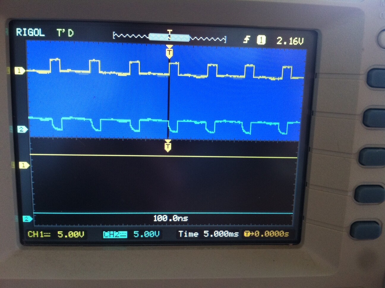
Hi everyone, I have checked everything and I monitoring on ( photo jpg) signal from ARDUINO on pin1 of U1 on channel 1(setting 5V). I monitoring on channel 2 signal on pin1 of U2 (setting 5V) looks normal.
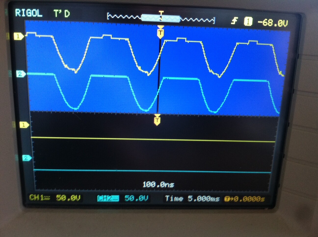
On photo(1)jpg you can see I am monitoring on channel1 voltage on pin4 ofU1 and channel 2 monitoring pin4 ofU2. This is looking totally wrong. Why this is happening to me? I do not see how it will switch on the MOSFET and how it will drain the charge at gate of MOSFET to switch off. I do not have any load or MOSFET in the schematic and I am waiting for new rectifier bridge ,because the one I (received 10 Each),do not give me full wave rectified picture. See on right upper corner of the oscilloscope, I have register -68V .Both probe ( channels)are set to monitoring DC
Hi,
Can you post a new up to date schematic please.
Can you mark on it where you are connecting the scope probes and the gnd clip of the probes when you show a multi channel scope diaplay.
All your scope patterns are of little help if you have a circuit with parts of it floating or biased with respect to the the
main reference point, where ever that is.
You must be aware that ALL of the scope probes' gnd clips are connected together and to gnd of your mains supply.
This may explain you blowing up probes and rectifiers and other components.
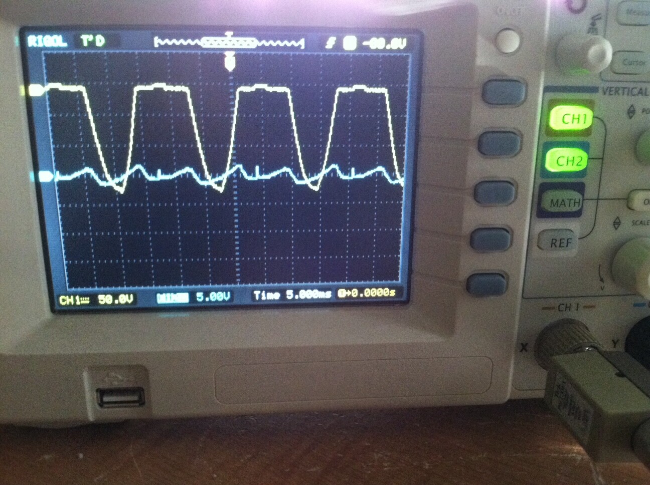
Yes, I follow this recommendations , but I have negative pattern for gate signal. I check voltage with my multimeter and is showing Vgs= +5.6V .
Where did you have the gnd probe of the scope connected for the negative pattern
Vgs = +5.6V would be correct as your reference is the MOSFET source.
Can I suggest before posting your images, you use a graphics editor, like PAINT and add some text pointing to what each trace is, some of your images you cannot read the CH numbers.
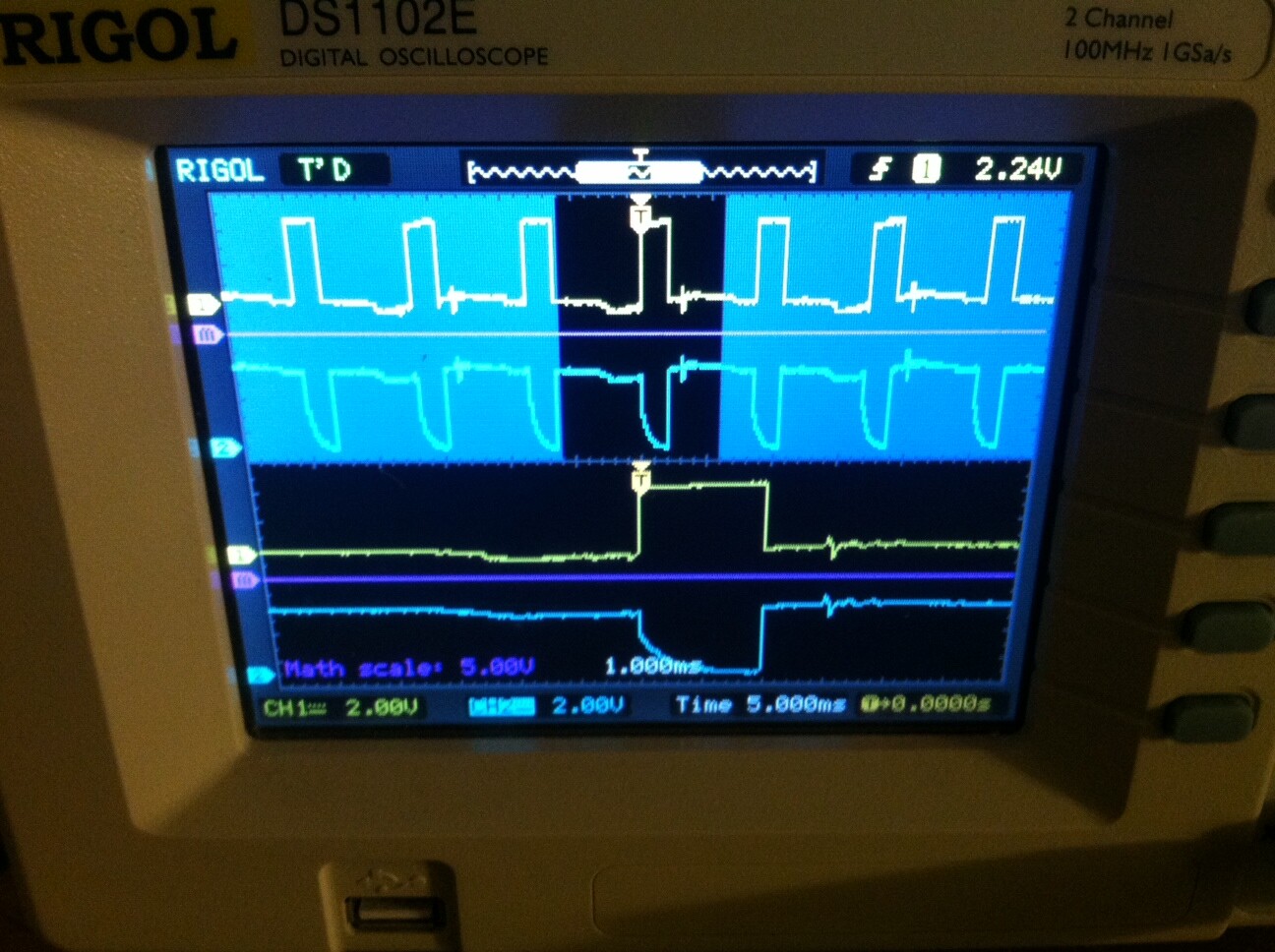
Sorry for this bad drawing. Like I sed I get back to original drawing , but for the test I do not connect L2 (or any resistor) and I did not connect the MOSFET.When I draw, I sow that it is bad Idea to monitoring Pin4 of U2, because this is directly connected to the GRD (or "-" of the bridge)
I set Chanel1 at scale 50V ,Chanel2 at 50V ,and math scale 10V, after that I lower to5V and going down steps up to100mV .No changes to Math line "0"V strait line.
Hi Tom, for the Arduino circuit both probe GND are connected at the point were ARDUINO GND is connected to the schematic. for the high voltage both probe GND are connected were "-" from the rectifier bridge is connected to the schematic .(I show on last posted schematic),but may be is not readable .
Now in the high voltage trace you have gnd of both probes connected to the -ve output of the rectifier.
You have Ch2 probe connected to pin4 of the lower 4N35, U2?.
Your circuit shows Pin4 connected directly to -ve output of the rectifier, so how are you able to measure a 68V signal.
You should have a flat trace at probe gnd reference.
PLEASE double check your wiring, TURN the power off and use your DMM to measure the resistance between -ve rectifier terminal and pin4 of the 4N35.
Can you use the full screen of the scope please for the two channels.
I don't see a need for a 100nS sweeping display when we are looking at 60Hz signals. so just get rid of it.
Resistance is 0.6 Ohm. looks like I have damaged GRN of my scope , that is why I have all this weird pictures that have no sense .
one more attempt. I install parallel to U1(4N35) optocoupler MOC3041 and connect pin 6 with same signal that is going to pin5 of U1 ,and you can see now what i have on channel 2 of my scope monitoring pin4 of this MOC3041.
dgueorguiev:
Looks like my scope adding half wave with minus value to the 0 V value of "-" point of the rectifier bridge. There no other explanation .
I would say you have damaged your scope, probably because you do not understand about gnd and mains supply.
Until you get the problem fixed, all you scope displays will be invalid.
Just the fact that you connect gnd of the probes to a DC rectifier that is DIRECTLY connected to the mains supply is where you scope will have been damaged.
DO NOT CONNECT gnds to ANY LIVE directly connected circuit.
Tom...