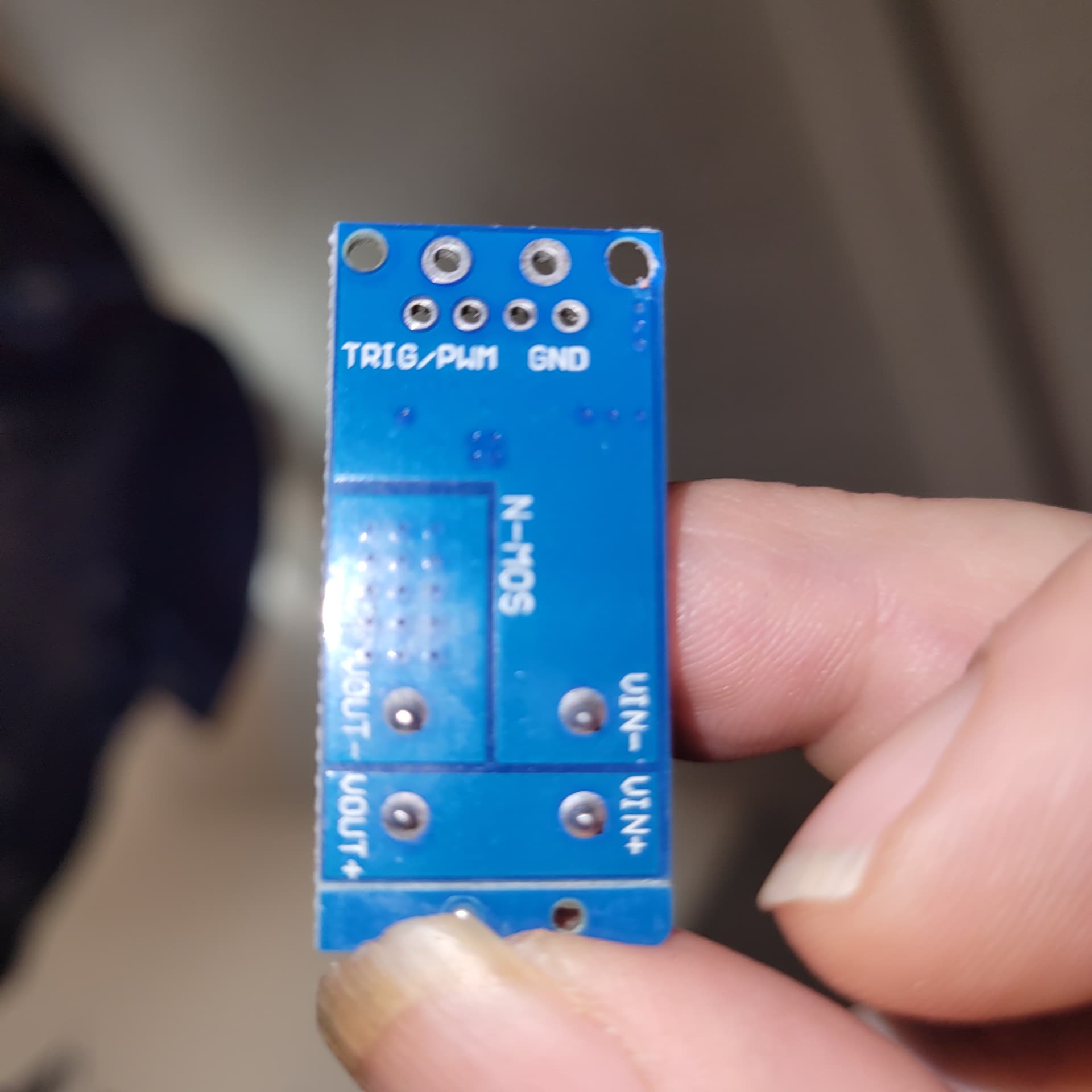
Does it make sense to exchange my 12v car injector signal for 5v signal, using one of these Mosfet switching boards? (to Nano.)
12v signal will be the trigger, and running 5 volts through the switch. (Those voltages are well within the specs of the switching board.)
The board is rated at 15a (max 30a) which is kind of high, I think.
(My fuel injectors are not connected. [I'm using the injector signal to meter fuel through another method.] Thus there should be no spike in the 12v)
Thanks guys.

If you want to convert a 12V signal to 5V for the Arduino, you can just as well use a transistor. There is hardly any current pulled from the circuit by an Arduino pin; you can check the IIH and IIL parameters in the datasheet of the Arduino.
You could use an optoisolator, they come in dual channel, cheap.
Inside they have a led and a detector, only light crosses between.
They also come rated to how many 1000's of V spikes they stop.
Not really but it will words.
Thus there should be no spike in the 12v)
Famous last works.
The MOSFET input signal has a max of 20V, and even a really really narrow spike will burn it out
2 Likes
OK thanks. There should be zero spike straight from the ecu. I don't have actual experience yet.
I'm open to other ideas. I do have these boards just sitting here. Is it something other than a spike that is not ideal? I'm fairly confident there will be no spike.
Whoh, I missed the first two replies. Let me read them.
OK thanks guys. Very informative.
Well, @sterretje already suggested a transistor and that should be fine. A bipolar NPN transistor like a 2N3904 costs under 50 cents and is pretty rugged. It will work fine to translate the 12V signal into a pull-down at the arduino pin with less impact on the driving circuit than an optocoupler. Hope this is legible: it's from a previous project with a similar need. Ignore everything besides the transistor and the base resistor ![]()

1 Like
What does eat spikes (like piezo getting smacked) is junctions like diodes. It makes a wider lower signal, I use 2 diodes for each lead like a kind of rectifier. GND pointing in, signal pointing out.
So perhaps a diode before the FET?
This will show how little I know;
but why does the input and output (across the "switch") require both, positive AND negative wires (dc in my case)?
Couldn't it just manipulate the positive one?
(Especially in my use here; a brushed motor going one direction)
What switch are you referring to?
OK good question.
I mean the VIN that is being switched.
Not the trigger.
The problem is I want control the duty pulses on three separate units.
I want to run 1 wire to each of the three units,
and ground each '-' coming out of the loads, to chasis.
I'm just confused why the mosfet requires both + and - of the dc.....or does it?
Oh I get it, the MOSFET probably uses power from the circuit.
That's fine.
I should be able to take ONLY the +OUT....
And not bother with -OUT.
Since I have chassis ground.
Am I correct?
You don't begin to understand possibly what electric flow is.
I'm just going to use the car's chasis instead of running black wires all over the place.
I thought about it, and see nothing wrong with it.
Maybe I didn't explain it well.
To review I have 3 mechanical solenoids.
They need a 50% 12v duty pulse. (So they don't overheat. [Which I've tested.]
The pulse is generated and sent by the Arduino.
The MOSFET Trigger Boards get their trigger signals from the Arduino, and chop the car's 12v and send to the respective solenoids when needed.
So between all these components, the ground should be able to handle the negative side of all the terminals.
Maybe a black wire from Arduino to trigger negative terminals.
3 MOSFET gates and 3 solenoids.
Does that make sense?
Any signal needs a return path.
One pin of J1 goes to the gate of the MOSFET, the other one comes back from the source of the MOSFET and provides the return path for the first one. Those need to be connected to your 12V.
Note: I do not know which pin on J1 is what; reversing the two pins might result in a damaged Arduino. So you will have to find the schematic of your module to be able to check.
OUT+ is connected to the drain of the MOSFET and will go to your Arduino input; you can use an external pull-up resistor or use the internal pull-up resistor. OUT- is connected to the source of the MOSFET and will go to the Arduino GND; this will complete the return path for OUT+.
Note
gate, source and drain are the names of the 3 pins of the MOSFET.
The thing I really dont understand is why there is two trigger (holes) and 2 ground (holes).
Edit: watching a video, the + (blue block) goes straight through the board.
There goes my idea.
But cant I just run my 12v+ through the MOSFET?
Then I could use chassis for ground?

You will have to measure with a multimeter or find the schematic. This looks very much like your module: https://www.robotics.org.za/XY-MOS?search=mosfet. There is unfortunately no schematic but it shows how it should be connected. Based on that, it's just for convenience.
Ah yes, exactly. Another video shows 2 small holes and one big hole are all conected.
This topic was automatically closed 180 days after the last reply. New replies are no longer allowed.