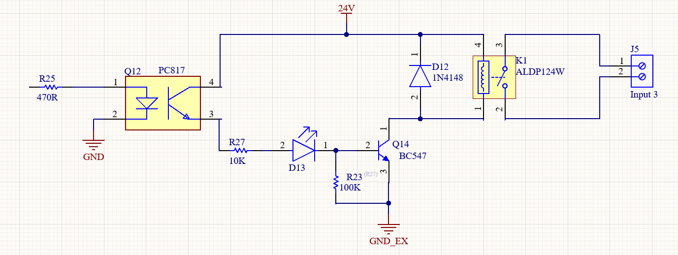
hi everyone. to control some loads with a STM32 board i designed the blow schematic. i want to know my design is ok? optocoupler is there because controller's power is isolated .
Your calculations look good. You can check how far away your calculations of Ib are really away from the minimal required base current. As the transistor is not normally a power type I assume a standard amplification of 100. It also is not required to drive the transistor into deep saturation.
I've not checked whether the optocoupler supports 24V.
As an optimization I'd put the LED in series with the relay coil with half transistor current. If the LED is too dark then put another resistor in parallel to the coil.
Your calculations look good. You can check how far away your calculations of Ib are really away from the minimal required base current. As the transistor is not normally a power type I assume a standard amplification of 100. It also is not required to drive the transistor into deep saturation.
so you mean in my calculation i must use 100 for hFE ?
I've not checked whether the optocoupler supports 24V.
As an optimization I'd put the LED in series with the relay coil with half transistor current. If the LED is too dark then put another resistor in parallel to the coil.
Vf of an IR opto LED is about 1.25volt. 4mA opto LED current is more than enough.
That calculates to 470 ohm.
I would leave the 100k between base and ground. It reduces leakage currents.
A 10k base CL resistor is fine.
10mA for an indicator LED is brutal.
1mA will most certainly do, unless you want the neighbours to also see it.
I would place the LED in the base circuit, not in the relay circuit.
Leo..
the coil resistance is 2880 ohm so its value was near the resistor i put. but i want to keep LED pararel to coil.
load is a 1" solenoid valve UNID-UW10-24VDC. but i cant find any detail about the coil resistance or amperage. i think relay easily can handel it.
i dont know why i did this mistake
so we are going to do with new values you give me
c = 8.3ma (Relay) + 1ma (LED D13)
Ic =10ma
somewhere i read you must double the current so
Ic = 20 ma
Ib × hFE = Ic
Ib(sat) × 100 = 20
Ib(sat) = 20/ 100
Ib(sat) = 0.2 ma // base current of transistor. its getting too little!!
so now base resistor :
R27 = Vi / Ib(sat)
R27 = 24V/ 0.2ma
R27 = 1.2K //base resistor
now optocoupler side:
CTR is about 50% so
led current= 0.2 /50% =0.4 ma <<<<< // this too it too little i dont know if its working
R25=(3.3v - 1.2v) / 0.4ma
R25=5100R // i rounded it
i dont think opto's led working with only 0.4 ma . do you think i go with minimum of 4 ma for opto's led and calculate the rest from there?
24V / 0.0002A = 120k
No harm if you use anything between 10k and 100k.
Yes. The "off" leakeage of the opto transistor is amplified by the transistor.
tiny x tiny is still not a lot, but the 100k resistor completely kills that.
Leo..
As said, if you put the indicator LED in the opto transistor circuit (collector or emitter), then you don't need R23.
An 1N4148 is more than capable for this relay.
Only use the 1N4007 for high voltage applications, like mains voltage.
The 1N4004 is better suited for low voltage applications, if... 1Amp is needed.
Leo..
Opto LED current with a 470 ohm resistor is about 4mA, which means that the opto transistor can switch at least 2mA without getting much out of saturation.
With a 10k base CL resistor, and indicator LED, and BE junction, and opto transistor in one circuit it only has to switch ~20volt/10k = 2mA. Right on the worst-case 50% of the opto.
Leo..
But I liked the LED in parallel with the relay like you wanted. It is an indicator, and as such might want to indicate that power is being delivered to the relay, not to the base of a transistor.
right. me too i liked parallel to relay coil. and its only 2 relays in board so two resistor is not too much difference, maybe in bigger design or mass products. but tanks to Wawa its a good practice for future designs
and another question, pc817 is cheap and i can find it everywhere but if i wanted a better and reliable option what do you recommend.