I'm still struggling with the current consumption from one off the Arduino's in my railway project.
Actually I have a lot of relay connected to the +5v to provide the closed or open signal back to the arduino.
The output of the relay (read status) , is read in the Arduino via a multiplexer.
Here the schema
The address for the multiplexer is set via D3/S0, D4/S2, D5/S1 and D6/S0 that's working fine.
The status of each individual relay (here in the schema just a simple NO switch) is read via Pin D7
The pin is declared as follows
#define muxData D7;
pinMode(muxData, input);
int status = digitalRead(muxData);
An other possibility (but not yet tried in real) is shown in following schema
As the relay is connected to the ground, I would you an input_Pullup and you can see in the code here
#define muxData D7;
pinMode(muxData, input_pullup);
int status = digitalRead(muxData);
I know that there is a difference in the signal. In the first option an open relay returns a false, and the second option an open relay returns a true. But the logic behind can be changed.
What is the better solution, taken into account that there are a lot of connection made to the Arduino.
Or is there no difference in both solution on the current consumption within the Arduino. (Which is limited)
That's completely correct.
The relay is closed by a manual button, or by a high signal from Arduino via Optocoupler and relay, or by a hardware contact on the railway, ...
It doesn't matter in my inital question.
Jim, No I didn't know.
Is started a few years ago with the first option to read the signals with the position of the turnouts.
Than added multiplexer to swith the turnouts to the right or to the left. Next I added Motor shields L298N to control the speed.
But now I think i have an issue that I ask to much from the Arduino Mega. It happens that the speed of the trains drops without any reason.
I'm busy to put all elements in a schematic.
Here already a first draft, but it's not complete yet.
I made also an inventory of all the connections: PWM steering via L298N
14 PMW ports used connected to L298N motor shield (2 x 7)
1 Digital output LOW value connected to all 14 motor shields
1 Digital output HIGH value conneced to all 14 motor shields
GND connected to the 7 L298N Motor shield
read/write digital signals via multiplexer
5v connected to 3 multiplexers CD74HC4067
4 digitial output to provide adress to the 3 multiplexers (Same pins used for all 3)
3 digitial output to enable the 3 multiplexers
1 digital write to set set the value via 1 multiplexer
2 digital read to read the value from 2 mutliplexer. This one I will change in Input-pullup
Wireless communication
Then I have a HC12 wireless shield connected
Optocoupler board
5v to a board with 16 optocouplers
GND connected to that board with 16 optocouplers
output of the bard is input for 1 multiplexer.
Turnout position
7 times 5v to relay to catch the signal back with the position of the turnouts.
7 times GND to this like explained in option 1 above.
GND to empty input of MUX (9x)
Relay shield for setting turnout
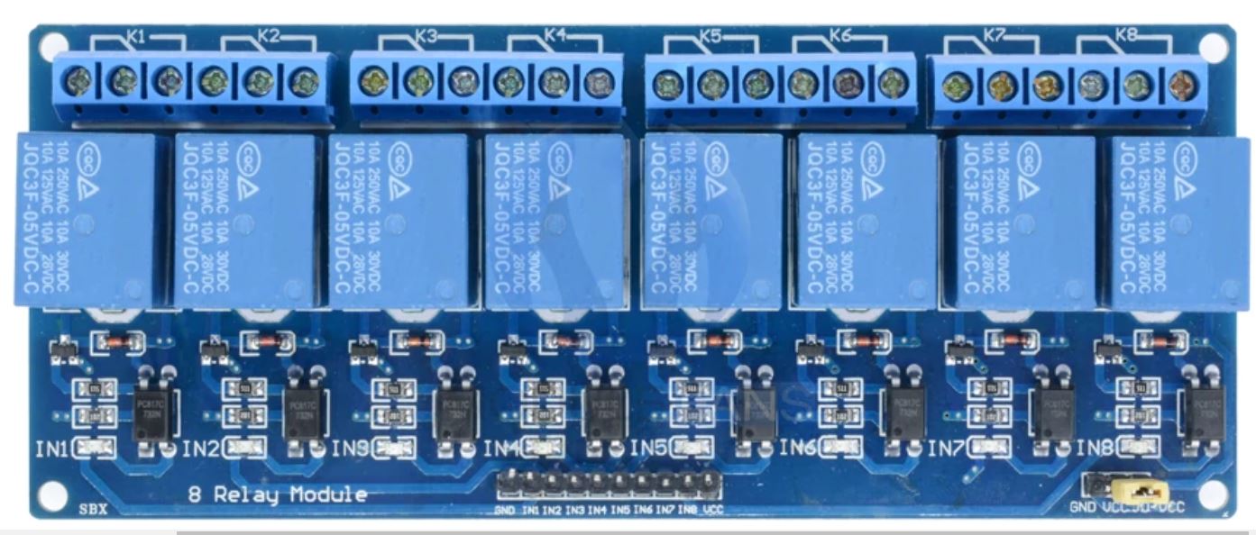
5v to 4 times a 8 port relay shield
Gnd to these relay shield
Digital in for the relais is via the multiplexer or
16 digital output to the Relay shield
Another point to mention:
If the arduino is connected to mu laptop via USB cable. there is no issue.
If it's connected via a standard adapter it happens some times.
I connected all the not used pins of the MUX C4 till C15 to the Ground.
If the Pinmode of the SIgnal pin is Input, then I get zero for every pin.
If the Pinmode of the signal pin is Input_Pullup I get all ones, also when the button is closed.
// Initialize the Mux CDH47HC4067
#define MUX4OUTMD 2  // EN

#define MUX4A0 3     // S0
#define MUX4A1 4     // S1
#define MUX4A2 5     // S2
#define MUX4A3 6     // S3
#define MUX4DATA 7   // Z

int mux4[16];

// the setup routine runs once when you press reset:
void setup() {
  // initialize serial communication at 9600 bits per second:
  Serial.begin(38400);

  //Set MUX MUX4A pins to output
  pinMode(MUX4A0, OUTPUT);
  pinMode(MUX4A1, OUTPUT);
  pinMode(MUX4A2, OUTPUT);
  pinMode(MUX4A3, OUTPUT);
  pinMode(MUX4OUTMD, OUTPUT);
  pinMode(MUX4DATA, INPUT_PULLUP);

  for (int i = 0; i < 16; i++) {
    mux4[i] = 0;
  }
}

// the loop routine runs over and over again forever:
void loop() {
  Serial.print ("mux4-");
  for (int i = 0; i < 16; i ++) {
    mux4[i] = ReadMux(i, MUX4OUTMD);
    Serial.print (mux4[i]);
    Serial.print (" ");
  }
  Serial.println(" ");
  delay(1000);        // delay in between reads for stability
}
int ReadMux (int port, int muxEN)
{
  digitalWrite(muxEN, LOW); // Disable
  digitalWrite(MUX4A0, (port & 1));
  digitalWrite(MUX4A1, (port & 3) >> 1);
  digitalWrite(MUX4A2, (port & 7) >> 2);
  digitalWrite(MUX4A3, (port & 15) >> 3);
  digitalWrite(muxEN, HIGH);
  int value = digitalRead (MUX4DATA);
  return value;
}
// For INPUTS:
// New and improved
// I made all the variable a byte, it will save RAM space
// You should also make mux4[16] a byte
byte ReadMux(byte port, byte muxEN) {
  byte value;

  digitalWrite(muxEN, HIGH); // Disable 4067
  digitalWrite(MUX4A0, (port & 1));
  digitalWrite(MUX4A1, (port >> 1) & 1);
  digitalWrite(MUX4A2, (port >> 2) & 1);
  digitalWrite(MUX4A3, (port >> 3) & 1);

  digitalWrite(muxEN, LOW); // Enable
  delay(1); // Wait for 4067 output to stabilize
  value = digitalRead(MUX4DATA); // Read the data
  digitalWrite(muxEN, HIGH); // Disable
  return value;
}
I don't know if the 4067 will work reliably for outputs.
Once the 4067 is disabled the outputs will float, that is, they
will be neither HIGH nor LOW.
You made need to use somehing like the 74HCT154 or two 74HCT138
Do you have a data sheet (or link to) for the relay board/module?
On the relay board are optocouplers.
In fact the relais is just used to set the turnout left or right with 15V AC.
So if the signal floats if 4067 is disabled, is not disturbing (I think)