Hello all,
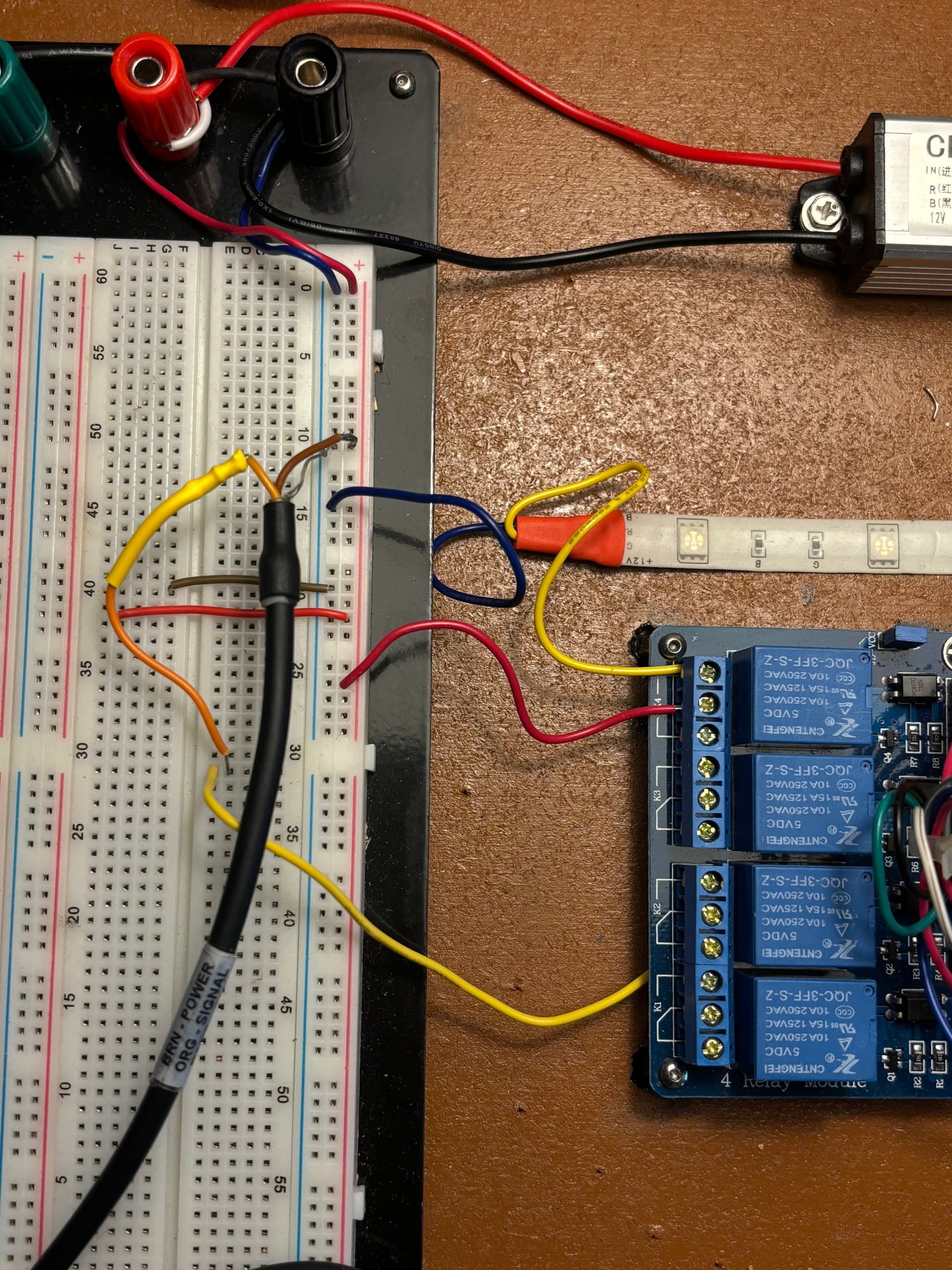
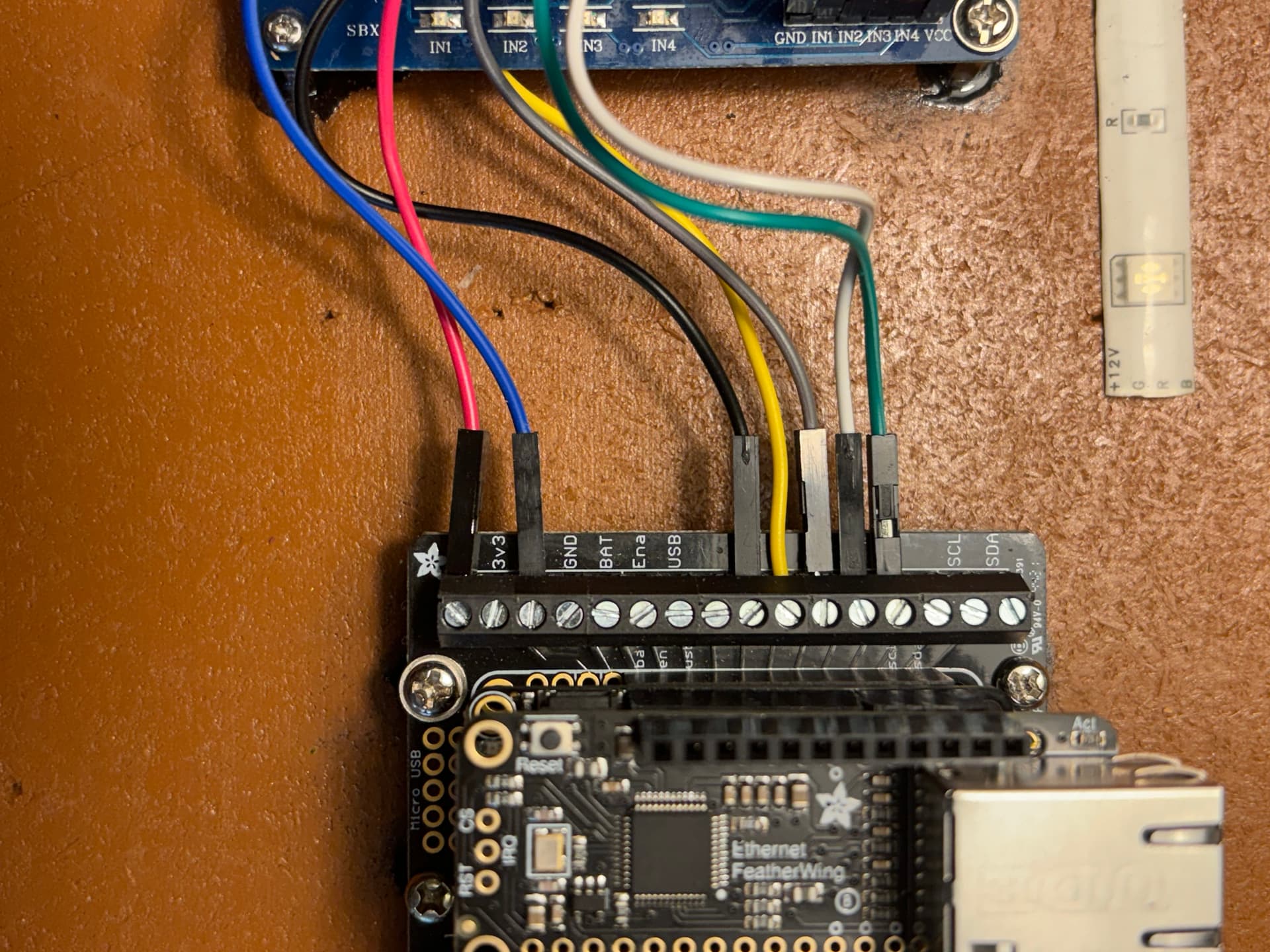
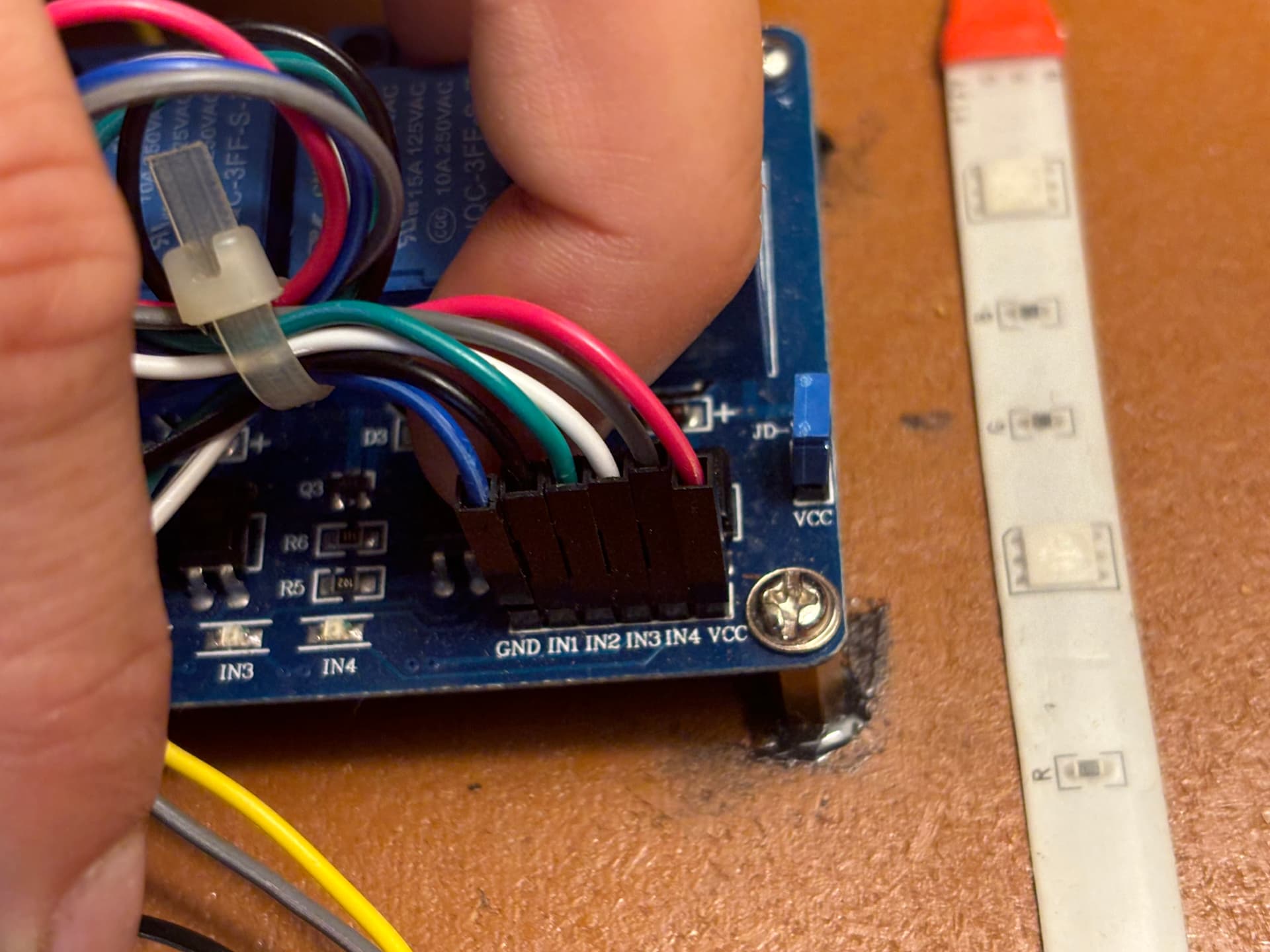
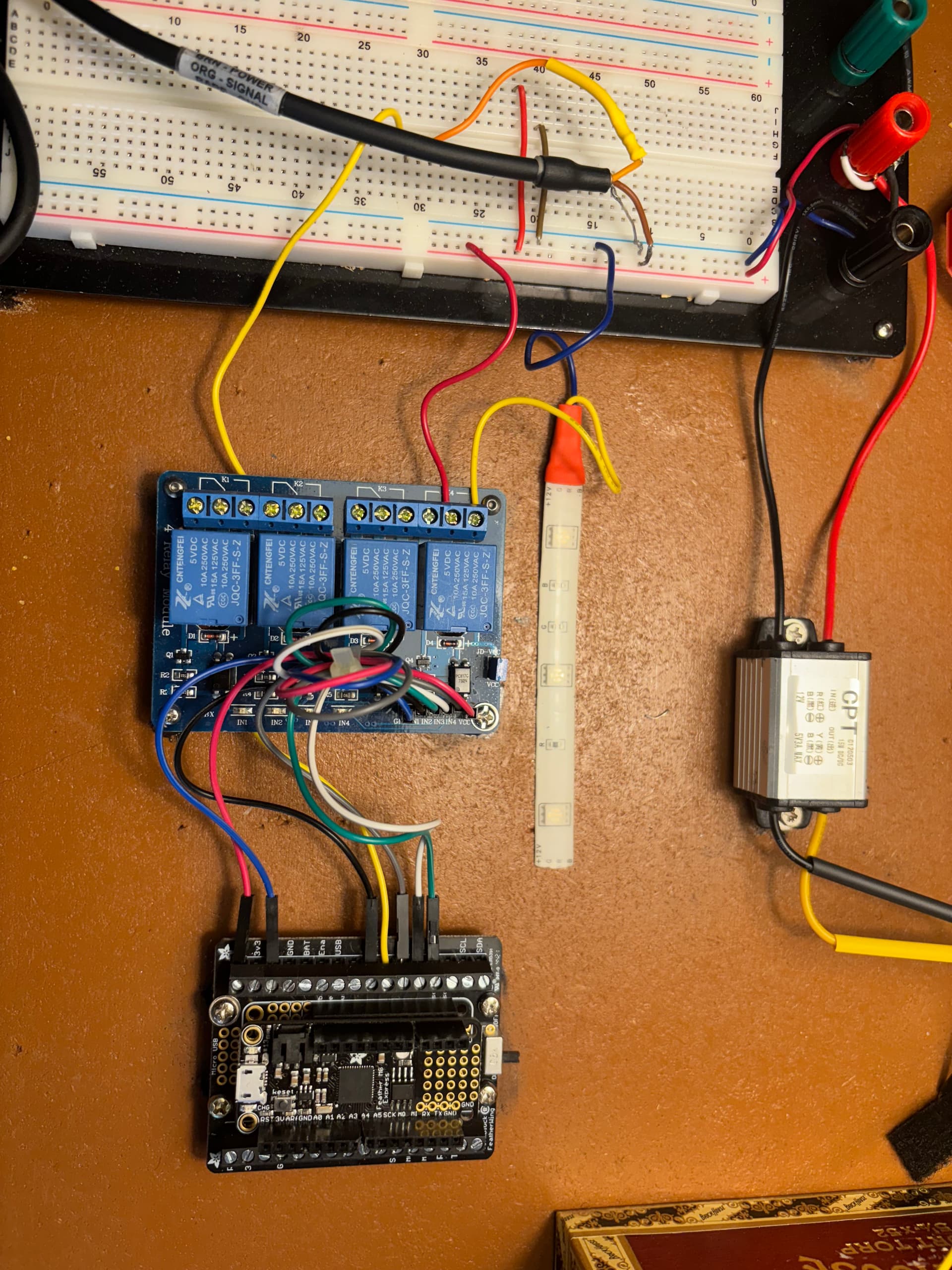
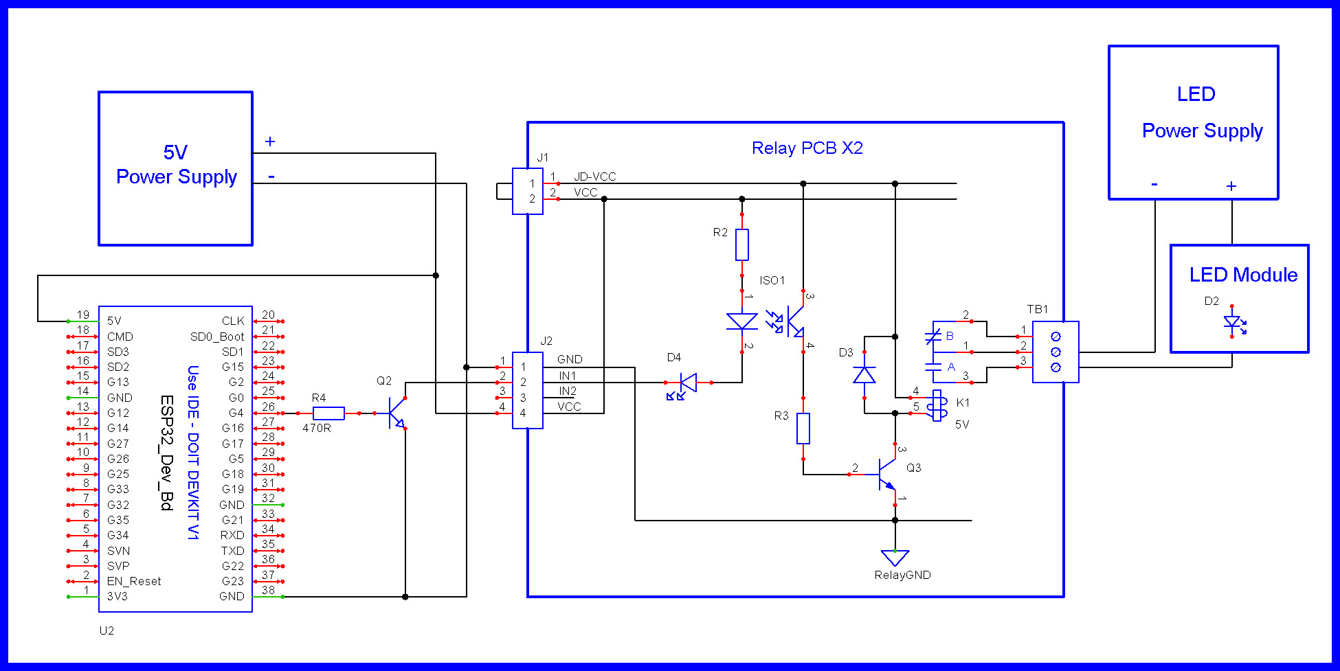
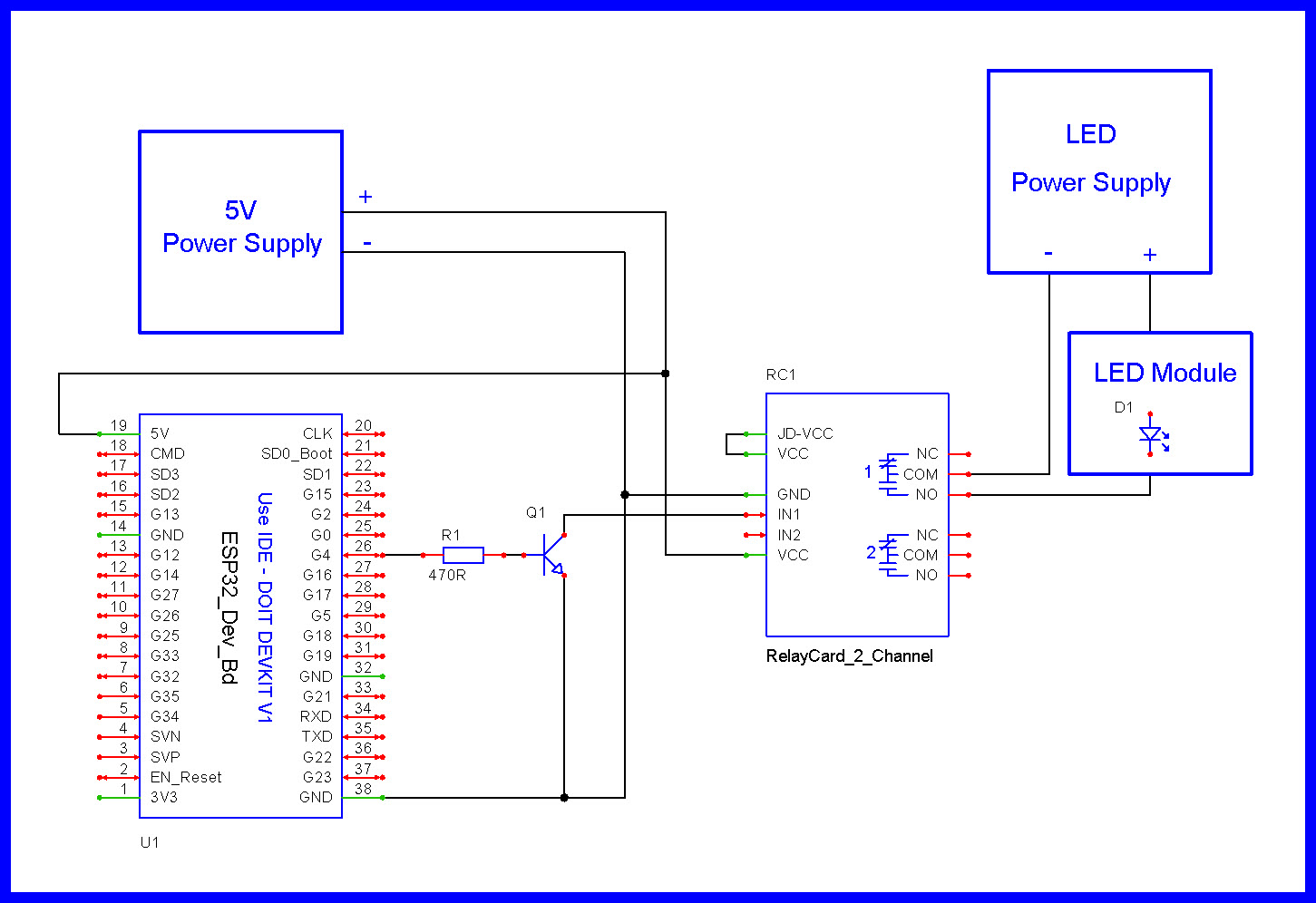
I am currently working on a precision irrigation project. The microcontroller I am using is the Feather M0 Express along with the Adafruit Ethernet FeatherWing, both stacked on the TermBlock FeatherWing terminal board. In short the whole system opens or closes solenoid irrigation valves via a relay board that is prompted to turn on or off by low soil moisture values picked up by Teros 12 soil moisture sensors. I have written three functions that work as expected independently from each other:
getSensorData : takes a reading from Teros 12 sensor and returns a float, volumetric water content(VWC).
activate_solenoid : uses a VWC reading and set parameters to turn on and off a specific relay valve.
data_to_adafruitIO : sends data to adafruitIO feed via ethernet.
the getSensorData and activate_solenoid functions work together as expected. When incorporating the data_to_adafruitIO function, the activate_solenoid function stops turning on and off the relay valve. the function still follows the same logic as before, but the digitalWrite(Valve, LOW) does not turn on the relay valve. through testing it seems that when the IO.run() function is included in the sketch, this behavior repeats. I am at a loss as to why the inclusion of this function would be affecting the digitalWrite() in activate_solenoid. The IO.run() function is necessary to maintain connection to the adafruitIO feed, so I am trying to figure out the cause of this bug and if I can work around it. thanks for your time, my code is as follows:
//login for Adafruit IO and ethernet library
#include "AdafruitIO_Ethernet.h"
#define IO_USERNAME  "username"
#define IO_KEY       "key"
AdafruitIO_Ethernet io(IO_USERNAME, IO_KEY);

//include SDI12 library
#include <SDI12.h>

//define SDI12 data pin
#define  DATA_PIN 11

//define soil sensor address
#define SOIL_SENSOR_1 1

//initialize SDI12 object "busSDI12" at data pin
SDI12 busSDI12(DATA_PIN);

//serial monitor baud rate
#define SERIAL_BAUD 9600

//set solenoid valve location
const int VALVE_4 = 10; // bottom black wire on left side of feather terminal in the field
//set timestamps for solenoid function

//timing variables for use in activate_solenoid
int start_of_time_buffer = 0;
int start_time_water = 0;

//set up the soil_moisture_sensor_1 feed
AdafruitIO_Feed *soil_moisture_sensor_1 = io.feed("soil_moisture_sensor_1");

void setup() {
  // Serial setup
  Serial.begin(SERIAL_BAUD);
  Serial.print("Starting Program...");
//prepare solenoid valve pin to output and set to closed
  pinMode(VALVE_4, OUTPUT);
  digitalWrite(VALVE_4, HIGH);
//SDI-12 setup
  busSDI12.begin();
  delay(500);
// connect to io.adafruit.com
io.connect();
// wait for a connection
while(io.status() < AIO_CONNECTED) {
  Serial.print(".");
  delay(500);
}
}
void loop() {
  // put your main code here, to run repeatedly:
  float DATA = getSensorData(SOIL_SENSOR_1);
  activate_solenoid(DATA, 0.1, 25000, 60000, VALVE_4);
  data_to_adafruitIO(DATA, soil_moisture_sensor_1);

}
//Function that returns VWC data from requested sensor address.
float getSensorData(int soilSensorAddress) {

  // Calls subFunction Measurement_Output() which calls TakeValue() which recieves returned value TakeMeasurement()
  // The result is stored into RAW1 an VWC1 which is echoed to the screen
  // The three subfunctions are presented in order of appearance for readability

  // Raw data coming from the Teros sensors
  float RAW = Measurement_Output(soilSensorAddress, 1.0, 0.0);


  // Volumetric Water Content
  float VWC = (3.879e-4)*RAW-0.6956 ;
  Serial.println(VWC);
  return VWC;

}


// Function allows the sensor to take a measurement and convert it into a float
float Measurement_Output(int Sensor_Address, float Slope, float Offset ){

  String raw_data = getValue(TakeMeasurement(Sensor_Address));
  float reading_actual = (raw_data.toFloat() * Slope) + Offset;
  return reading_actual;

}

String getValue(String data){
  char separator= '+';
  int index= 1;
  int found = 0;
  int strIndex[] = {0, -1};
  int maxIndex = data.length()-1;

  for(int i=0; i<=maxIndex && found<=index; i++){
    if(data.charAt(i)==separator || i==maxIndex){
        found++;
        strIndex[0] = strIndex[1]+1;
        strIndex[1] = (i == maxIndex) ? i+1 : i;
    }
  }
  return found>index ? data.substring(strIndex[0], strIndex[1]) : "";
}

String TakeMeasurement(int Sensor_Address){

  //Setup the command measuremt cmd
  String Command = "";
  Command += Sensor_Address;
  Command += "M!";
  busSDI12.sendCommand(Command);
  delay(2000);
  busSDI12.clearBuffer();


  //set up data request cmd
  Command = "";
  Command += Sensor_Address;
  Command += "D0!";

  String Measurement = "";    //Assigning an output

  //Starting bus and sending command

  busSDI12.sendCommand(Command);
  delay(30);

  //Compliling reading and appending to the empy output string
  while(busSDI12.available()){
    char c = busSDI12.read();
    if ((c != '\n') && (c != '\r')) {
      Measurement += c;
      delay(10);  // 1 character ~ 7.5ms
    }
  }
  busSDI12.clearBuffer();

  return Measurement;   // Returning raw measurement
}

//This is what the activate_solenoid function does when it is listed in the main loop
//activate_solenoid function checks to make sure buffer period has passed in order to water when VWC is below threshold
void activate_solenoid(float VWC, float threshold, int buffer, int watering_length, int Valve) {
  //get variable on current time
  int currenttime = millis();
  Serial.print(currenttime);
  Serial.println("  is the current time (ms)");
  //using currenttime - the time stamp variable (denotes amount of time buffering)
  int actual_buffer = currenttime - start_of_time_buffer;
  int actual_water = currenttime - start_time_water;
  //check if VWC is under watering threshhold
  if (VWC < threshold){
    //if greater than or equal to buffer time, check watering period variable and set buffer time variable to current time
    Serial.println("VWC is below threshold");
    if (actual_buffer == currenttime){
      start_of_time_buffer = currenttime;
      Serial.println("Buffer period has begun");
    }
    else if (actual_buffer >= buffer){
    //if watering period variable equals zero, water!
      if (actual_water == currenttime){
        digitalWrite(Valve, LOW);
        start_time_water = currenttime;
        Serial.println("Buffer period over, time to water!");
      }
      //if watering period is greater than or equal to watering length of time, set watering period to zero and buffer time variable to current time
      else if (actual_water >= watering_length){
        digitalWrite(Valve, HIGH);
        start_time_water = 0;
        start_of_time_buffer = currenttime;
      }
    }
  }
  if (VWC >= threshold){
    if (actual_water != currenttime && actual_water >= watering_length){
      digitalWrite(Valve, HIGH);
      start_time_water = 0;
      start_of_time_buffer = currenttime;
      Serial.println("VWC is above threshold and watering period is over.");
    }

  }
}
void data_to_adafruitIO(float VWC, AdafruitIO_Feed* soilsensoraddress){

  // io.run(); is required for all sketches.
  // it should always be present at the top of your loop
  // function. it keeps the client connected to
  // io.adafruit.com, and processes any incoming data.
  io.run();

  // send real Soil moisture data to tested keys
    soilsensoraddress->save(VWC);
    delay(1000);

}