/*
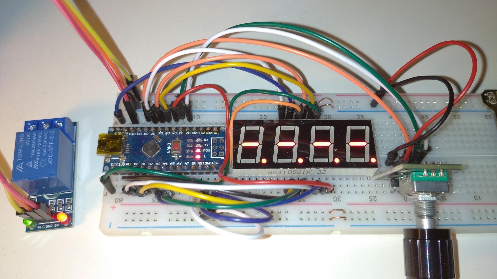
Relay timer - User settable timer controlling a relay output
Implementation 2 - Arduino outputs directly runs LED segments
Hardware requirements
Function
- Arduino manages the display as a multiplexed POV refresh using direct I/O
- Rotary encoder allows setting the required timer value
- Rotary encoder switch used to start the timer
- Timer can be paused with a press of switch. Second press resumes and long press ends the timer.
- While timer is active (running or paused) the relay output is switched on.
Circuit Connections
+---------+--------------------+
| Arduino | Connected to |
+---------+--------------------+
| D0 | N/C (Arduino Rx) |
| D1 | N/C (Arduino Tx) |
| D2 | Rotary Encoder B |
| D3 | Rotary Encoder A |
| D4 | LED pin 6 (dig 4) |
| D5 | LED pin 8 (dig 3) |
| D6 | LED pin 9 (dig 2) |
| D7 | LED pin 12 (dig 1) |
| D8 | Selection Switch |
| D9 | N/C |
| D10 | Relay Output |
| D11 | N/C |
| D12 | LED pin 11 (seg A) |
| D13 | LED pin 7 (seg B) |
| A0 | LED pin 4 (seg C) |
| A1 | LED pin 2 (seg D) |
| A2 | LED pin 1 (seg E) |
| A3 | LED pin 10 (seg F) |
| A4 | LED pin 5 (seg G) |
| A5 | LED pin 3 (seg DP) |
+---------+--------------------+
Library Dependencies
MD_KeySwitch and MD_REncoder can be found at GitHub - MajicDesigns/MD_KeySwitch: KeySwitch Digital Input Library - SUPERCEDED - See README
Revision History
Feb 2016 - version 1.0
Copyright
Copyright (C) 2015 Marco Colli. All rights reserved.
This is free software; you can redistribute it and/or
modify it under the terms of the GNU Lesser General Public
License as published by the Free Software Foundation; either
version 2.1 of the License, or (at your option) any later version.
This software is distributed in the hope that it will be useful,
but WITHOUT ANY WARRANTY; without even the implied warranty of
MERCHANTABILITY or FITNESS FOR A PARTICULAR PURPOSE. See the GNU
Lesser General Public License for more details.
You should have received a copy of the GNU Lesser General Public
License along with this library; if not, write to the Free Software
Foundation, Inc., 51 Franklin St, Fifth Floor, Boston, MA 02110-1301 USA
*/
#include <MD_REncoder.h>
#include <MD_KeySwitch.h>
// Debugging stuff -------------------------
#define DEBUG 0
#if DEBUG
#define PRINTS(s) Serial.print(F(s));
#define PRINT(s, v) { Serial.print(F(s)); Serial.print(v); }
#define PRINTX(s, v) { Serial.print(F(s)); Serial.print(F("0x")); Serial.print(v, HEX); }
#else
#define PRINTS(s)
#define PRINT(s, v)
#define PRINTX(s, v)
#endif
// Hardware pin definitions ---------------
// Rotary Encoder
const uint8_t RE_A_PIN = 3;
const uint8_t RE_B_PIN = 2;
// Selection key
const uint8_t SEL_PIN = 8;
// Control output
const uint8_t OUTPUT_PIN = 10;
// Digit multiplex selection - [0] is least sig dig (LSD), [n] is MSD
const uint8_t digitPin[] = {4, 5, 6, 7 };
// Segment multiplex selection - in order segments A B C D E F G DP
const uint8_t segmentPin[] = { 12, 13, A0, A1, A2, A3, A4, A5 };
// Static Data tables ----------------------
// LED segments are defined as uint8_t values with bits mapped as follows:
// MSB LSB
// +----+-----------------+
// |Bit | 7 6 5 4 3 2 1 0 |
// +----+-----------------+
// |Seg |DP G F E D C B A |
// +----+-----------------+
// LED segments for digits
const PROGMEM uint8_t digits[] =
{
0x3f, 0x06, 0x5b, 0x4f, // 0123
0x66, 0x6d, 0x7d, 0x07, // 4567
0x7f, 0x6f //89
};
// LED segments for alpha characters
const PROGMEM uint8_t alpha[] =
{
0x77, 0x7c, 0x39, 0x5e, 0x79, 0x71, // ABCDEF
0x3d, 0x76, 0x06, 0x0e, 0x00, 0x38, // GHIJKL
0x00, 0x54, 0x3f, 0x73, 0x67, 0x60, // MNOPQR
0x6d, 0x78, 0x3e, 0x3e, 0x00, 0x00, // STUVWX
0x6e, 0x5b // YZ
};
const uint8_t DECIMAL = 0x80;
// Miscellaneous ---------------------------
#define ARRAY_SIZE(a) (sizeof(a)/sizeof(a[0]))
// Digital state to turn each digit on or off during multiplexing
const uint8_t DIGIT_ON = LOW;
const uint8_t DIGIT_OFF = HIGH;
const uint8_t SEGMENT_ON = (DIGIT_ON == HIGH ? LOW : HIGH);
const uint8_t SEGMENT_OFF = (DIGIT_OFF == HIGH ? LOW : HIGH);
// Finite state machine states
typedef enum state_t { S_INIT, S_IDLE, S_START, S_RUNNING, S_PAUSE, S_END };
// All time duration b=values for setup and storage are held in units of
// the smallest time interval, in seconds. This is translated into minutes
// and seconds for the display and countdown.
const uint8_t TIME_MAX_MINUTES = 99;
const uint8_t TIME_INTERVAL = 5; // smallest time interval in seconds
const uint16_t TIME_MAX_SP = ((TIME_MAX_MINUTES * 60) + 59) / TIME_INTERVAL; // max setting value
// Global Objects --------------------------
MD_KeySwitch SW(SEL_PIN);
MD_REncoder RE(RE_A_PIN, RE_B_PIN);
// Code ------------------------------------
void updateSegments(uint8_t val)
// update the segments with the value specified
{
for (uint8_t i=0; i<ARRAY_SIZE(segmentPin); i++)
{
digitalWrite(segmentPin[i], (val & 1 ? SEGMENT_ON : SEGMENT_OFF));
val >>= 1;
}
}
void displayMessage(char *pMesg, uint16_t duration = 2000)
// Display the message specified for the specified duration in milliseconds
{
uint32_t startTime = millis();
char *p; // temporary string pointer
uint8_t v; // LED pattern for display
while ((millis() - startTime) < duration)
{
p = pMesg;
for (int8_t i = ARRAY_SIZE(digitPin) - 1; i >= 0; i--)
{
if (*p != '\0')
{
v = pgm_read_byte(alpha + toupper(*p) - 'A');
p++;
}
else
v = 0;
  // turn all the digits off
  for (uint8_t j = 0; j < ARRAY_SIZE(digitPin); j++)
    digitalWrite(digitPin[j], DIGIT_OFF);

  // SPI transfer of new data
  updateSegments(v); // send value

  // show new data
  digitalWrite(digitPin[i], DIGIT_ON);
}
}
}
void displayTime(uint16_t val, uint8_t decDigit = 0)
{
uint8_t dig = 0;
for (uint8_t i=0; i<ARRAY_SIZE(digitPin); i++)
{
dig = val % 10;
val /= 10;
// turn all the digits off
for (uint8_t j=0; j<ARRAY_SIZE(digitPin); j++)
  digitalWrite(digitPin[j], DIGIT_OFF);

// SPI transfer of new data
updateSegments(pgm_read_byte(digits + dig) + (decDigit == i ? DECIMAL : 0)); // send value

// show new data
digitalWrite(digitPin[i], DIGIT_ON);
}
}
void setup()
{
#if DEBUG
Serial.begin(57600);
PRINTS("[Timer]\n");
#endif // DEBUG
RE.begin();
SW.begin();
// initialise hardware
pinMode(OUTPUT_PIN, OUTPUT);
for (uint8_t i = 0; i<ARRAY_SIZE(digitPin); i++)
{
pinMode(digitPin[i], OUTPUT);
digitalWrite(digitPin[i], DIGIT_OFF);
}
for (uint8_t i = 0; i<ARRAY_SIZE(segmentPin); i++)
{
pinMode(segmentPin[i], OUTPUT);
digitalWrite(segmentPin[i], SEGMENT_OFF);
}
displayMessage("helo");
}
void loop()
{
static state_t state = S_INIT;
static uint16_t setPoint = 0;
static int8_t minutes = 0, seconds = 0;
static uint32_t timeStart = 0;
static boolean inMessage = false;
if (!inMessage)
displayTime((minutes*100)+seconds, 2);
switch (state)
{
case S_INIT:
PRINT("\nS_INIT set:", setPoint);
{
uint16_t totalSeconds = setPoint * TIME_INTERVAL;
seconds = totalSeconds % 60;
minutes = totalSeconds / 60;
  if (minutes > TIME_MAX_MINUTES) minutes = TIME_MAX_MINUTES;

  state = S_IDLE;
}
break;
case S_IDLE: // handle user input or just wait
//PRINTS("\nS_IDLE ");
// rotary encoder block
{
uint8_t x = RE.read();
  switch (x)
  {
  case DIR_CW: PRINTS(" CW");  if (setPoint < TIME_MAX_SP) setPoint++; break;
  case DIR_CCW: PRINTS(" CCW"); if (setPoint > 0) setPoint--; break;
  }
  if (x != DIR_NONE) state = S_INIT;
}
// switch block
if (SW.read() == MD_KeySwitch::KS_PRESS && setPoint != 0)
{
  PRINTS(" Press");
  state = S_START;
}
break;
case S_START:
PRINTS("\nS_START");
timeStart = millis();
digitalWrite(OUTPUT_PIN, HIGH);
state = S_RUNNING;
break;
case S_RUNNING:
PRINTS("\nS_RUNNING");
// Time counter
if(millis() - timeStart >= 1000)
{
timeStart += 1000;
if (seconds != 0)
seconds--;
else
{
seconds = 59;
if (minutes != 0)
minutes--;
else
state = S_END;
}
}
// Check if pausing
if (SW.read() == MD_KeySwitch::KS_PRESS)
{
PRINTS(" Pause");
state = S_PAUSE;
}
break;
case S_PAUSE:
PRINTS("\nS_PAUSE");
inMessage = true;
displayMessage("pause", 50);
{
uint8_t x = SW.read();
  switch (x)
  {
  case MD_KeySwitch::KS_PRESS:
    PRINTS(" Restart");
    timeStart = millis();   // approximate, but we have paused so accurate time is out the window
    inMessage = false;
    state = S_RUNNING;
    break;

  case MD_KeySwitch::KS_LONGPRESS:
    PRINTS(" Stop");
    inMessage = false;
    state = S_END;
    break;
  }
}
break;
case S_END:
PRINTS("\nS_END");
digitalWrite(OUTPUT_PIN, LOW);
displayMessage("end");
state = S_INIT;
break;
default:
PRINTS("\nDEFAULT");
state = S_IDLE; // in case we get into trouble!
break;
}
}