Hi everyone, I m new here. I'm software developer but I m no so strong in electronic subject.
I have some doubt about snubber and AC power source.
My new project contains a relay that switch on/off a power supply 12v. I notice, doing some "quality" check on my system that up to relay switch on, there is a little transient spike on vcc pin of my micro. That spike it is around 10 v, for few nanos sec.
I investigate in deep and I notice that the noise happens only with loaded connected to relay, so it isn't related to relay coils inductive load.
I read somewhere that for this kind on inducted noise an rc snubber can help. I saw too that it is placed between relay endpoint.
I have some doubts about it.
Is it the right way to wire the snubber? and, if yes, does a small amount of current flow in the circuit when the relay is open!?
Sorry if my question seems stupid but as my knowledge in electronic are limitated
However, noise is not usually that easy to fix because it has all kinds of causes. Often missed is loops of wire, which are perfect for picking up both wanted and unwanted signals of all kinds, and poor layout of ground and 0V connections.
How do you know? Something of such a short duration is easily suppressed with a 0μ1 ceramic capacitor on the pin in question, with the other end to 0V.
It would be helpful to see a schematic (hand drawn and photographed is fine) and some clear photos of what you have made.
Thanks a lot, I will procede to provide more details soon as possible.
About the RC snubber, if I put It across relay terminals, in presence of AC, does it let flow a Little bit of current in the circuit also when relay is open? Or not!?
Ah ok, I imaging due to small size of capacitor.... So, if let the system running 24/7, 99% with relay off, my bill will not affected by the snubber, right?
Of course, I will post circuit tomorrow. I m switching the VAC input of Power supply 12, that it is rated as 120W. The noise appear only when load Is connected. If I switch the relay unconnected, the scope don't catch any spike
The snubber has a capacitor in series with a resistor. On AC, a minute amount of current will seem to flow through the circuit. IS that a problem? If so, then use ferrite cores or clip-on ferrite device to limit the radiated RF.
Thanks a lot, you target exactly my lacks. I wasn't aware about wattless current.
So, in some way It isn t the current billed, but the emf used from the provider to push that current.... If the current Just load a capacitor and came back to them, that current is not accounted, because they recover the effort done. Instead, if there is a resistor in the circuit, that energy is transformed in heat, don't came back to them, and is payed. Is more or less like that?
I think that's a pretty good description. If you wish to continue reading search for I squared R losses, which lead on to the reason electricity is transmitted at high voltage. Then ask yourself what happens to all that current going backwards and forwards doing nothing useful.
I did some test with this snubber purchased from amazon Snubber RC
No remarkable results
I try to put it across the load, without any improvements, then I try to put it across the relay terminal, with some improvement, but with huge side effect, the power supply 12v controlled by relay, begin
to switch on and off intermittently also when relay is "open". (3 sec off, 0.2 sec on, more ore less)
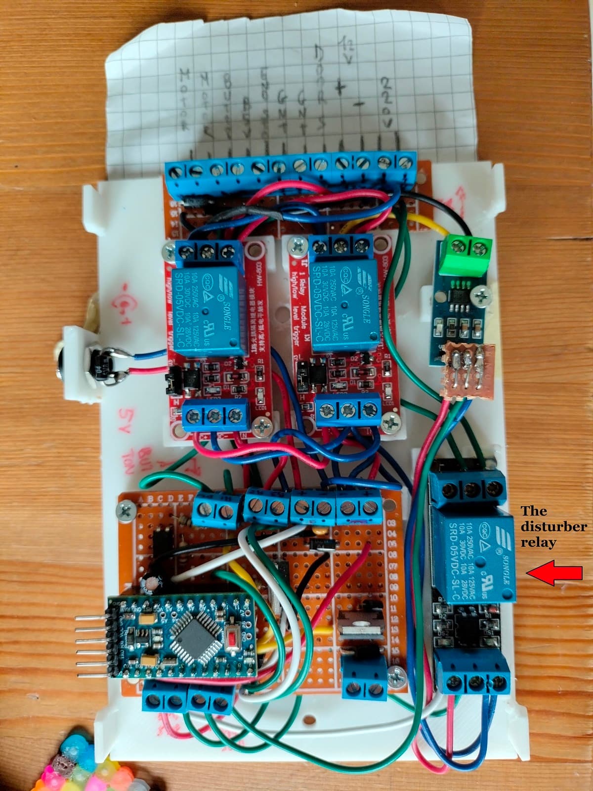
From following link some more details about the problem, some picture of circuit ecc.
(plese don't take care about the gray window box on scope screenshot, my cheap scope is bugged, doesn't report cursor lines when save image, so that info referred to it became useless)
I would think the main problem is the messy wiring*, with little attempt to keep signal and logic wires away from high current switched wires, combined with loops passing near each other. Build it again taking care to keep high current and low current wiring separate and pay attention to where the current flows. To minimise noise pick up the current to and from any part should flow in adjacent wires much as is the case with any mains cable where the wires are closely together. This isn't just neat and convenient, it is good electrical practice.
If you said where you are measuring the problem I missed it; I don't just mean where you have the oscilloscope probe I mean where you have it grounded to the circuit.
Please draw a better schematic, hand drawn and photographed is fine, just make it accurate. For example you have a mystery wire from the Arduino to RL3, no idea what that does. Your power source is unclear and is marked for both AC and DC, very confusing. Lots of wires that do not connect to anything.
*I wish I had photos of my first attempt to make a hi-fi amplifier; it was a disaster. It would be a good example to show here of how not to lay out a circuit. It howled and made all sorts of horrible noises. At the time I didn't have a clue why it didn't work, now I know it was embarrassingly bad.
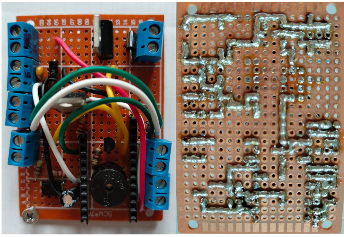
Oh, neat device, clever use of space. You could argue that if it works without a problem then don't worry about it!
You addess again to the problem. I try to use online service to draw. It have not the exact component that I used. And futhermore the free trial terminate in the middle of my work. I will proceed to move away the high voltage wires from others, I will proceed with definitive installation of everything, removing the "spaghetti style", and I will repeat the test.
Here were I attach the probe to test . Is it ok? or I should connect the ground nearest to input gnt?
See this How to get the best out of this forum for advice on creating a schematic. A rough but accurate hand drawn schematic is far more useful than a neat one with missing or inaccurate information.


