It wouldn't help. Erasing the EEPROM is the same as writing to it. You need a Plan B.
This type of memory may be an option. Seems overkill though. 8Kbytes of it and you need... 4 bytes!
It wouldn't help. Erasing the EEPROM is the same as writing to it. You need a Plan B.
This type of memory may be an option. Seems overkill though. 8Kbytes of it and you need... 4 bytes!
Hi
Just to get your problem straight.
You have two controls that set the position of your motors they are pots.
So when you turn the pot it places the motor drive to a certain position corresponding to the pot position.
When you power down and power up the motors move?
Is that right?
Why do they move when you are using the pots as the position selector.
If the pot has not been moved between power down and power up the motors should not move.
The pots are your memory.
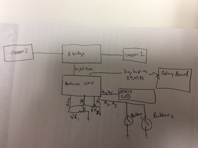
Can you please post a copy of your circuit, in CAD or a picture of a hand drawn circuit in jpg, png or pdf?
Tom..... ![]()
yes that is correct. let me see what I can draw real quick
here it is
TomGeorge:
If the pot has not been moved between power down and power up the motors should not move.
The pots are your memory.
Certainly worth a try. Just need to set the motor positions in startup() based on an initial pot reading. You would need a "calibrate" button as well though, to get the motor to go through the process it currently goes through at startup. This would fix things if the pots get accidentally moved while the power is off.
Hi,
So you don't have position feedback from the stepper........okay.. :-X
Can I suggest when you do an analog read, you do it twice.
There is only one AtoD in the arduino, changing from one input to another and inquisition of a valid level takes time.
So do a
val = analogRead(A0);
val = analogRead(A0);
The first read is assumed to be during acquisition, so the next read will be valid.
This may fix your jitter problem.
Unfortunately as I see in your sketch, you may have to do some work to get this configuration to work.
Tom..... ![]()
Bear with me. I am very new to this. Where would I place this in the sketch?
Tnx Jim
TomGeorge:
Unfortunately as I see in your sketch, you may have to do some work to get this configuration to work.
No, that would be easy:
void adjust(int sensorPin, AF_Stepper &stepper, int &pos, int lcdx, int lcdy, byte buttonPin, ButtonV2 &button, int RELAYx, int RELAYy, int lcda, int lcdb, unsigned long &lastStepperAdjustTime) {

  int prevPos = pos;
  unsigned long timeNow = millis();
  int discard = analogRead(sensorPin);  <--- ADD THIS LINE
  int val = map(analogRead(sensorPin), 0, 1023, 0, 5000);   //get the potentiometer value
But I thought I read in a recent post that the jittering was fixed now, possibly by replacing 100K pots with 10K pots and/or adding some small caps?
Paul
I added that line it seems to help a little. I am using a 500 ohm pot, I need to dig up a 10K pot an use that. I thought (several posts back) that the problem of the jitter had been fixed, I had made several large position changes with the pot, but as soon as I made small movements the jitter problem surfaced. I also left the setup running over night and when I cam back tot eh desk i noticed the motor trying to make a step.
I will run down a buy a couple 10 k pots and see how that works.
next question is
when the LCD prints the position say from 4 to 25 and the back to 4 as an example there ends up being a 0 once the number of the position is less that 10. I am having a similar issue with a timer where after 59 seconds the second display show 19, 29, ...99 the 10 seconds once 10 seconds has passed into the next "new " minute. how do I fix this. I tried an lcd.clear(); but that just makes the LCD not work correctly.
anyways thank you so much for your help. I Have been reading lots trying different code sketch learning these devices, much different than the RF world I am used to.
Try changing this
lcd.print(map(pos, 0, 5000, 0, 100));
to
    char buff[3];
    sprintf(buf, "%2d", map(pos, 0, 5000, 0, 100));
    lcd.print(buf);
or
    int i = map(pos, 0, 5000, 0, 100);
    lcd.print(i / 10);
    lcd.print(i % 10);
Question for you: the pot value has range 0 to 1023, the motor position between 0 and 5000, but on the lcd display it is only shown as whole percentage. What level of accuracy is actually needed for adjusting the antenna tuning?
Hi,
Have you got any hysteresis built into the positioning program?
Tom... ![]()
I don't think there is any hysteresis built in
PaulRB has been helping me write, really writing much of it and telling me what to change. Extremely helpful to say the least.
I would like to have 1/10% accuracy. I think that could be achieved using a 10 turn pot. Sometimes the slightest change in inductance or capacitance can make a difference. I am always trying to adjust for the best return loss ( ideal is -40db). But really -20db is just fine.
I am thinking about moving the build to an mega board that way I can eventually and a VSWR sensor to be able to display the match on the same LCD instead of having a separate SWR meter
Have you though about using pairs of ordinary (single turn) pots? One for "course" to control the whole percentage 0..99 and one for "fine" to control the fraction of the percentage 0.00..0.99. This would give you the resolution to control your steppers down to single steps. Also the pots would not suffer from jittering or noise or need smoothing or hysteresis. You would need to use a total of 4 analog inputs, but you have 6 on an Uno.
Not sure why you think you need a Mega. Remind us how many pins each of your components are using? If you need to reduce use of pins, there may be easier ways. For example you currently have only one device on your i2c bus. An i2c i/o extender like this would allow you to control your 4 relays and read 4 buttons via the bus, freeing up 8(?) pins.
There are also i2c analog input modules like this which have 4 inputs for 4 pots, freeing up those on the Uno.
I didn't know I could use 2 pots for each stepper. That would actually be better. I think it would be much easier to adjust. So I like that idea.
I was thinking about going to the mega because I figured I would need additional pins for sensors. Eventually I want to add a VSWR sensor. Using a directional coupler I could display the return loss of the antenna as it is tuned. And to include an analyzer function that could calculate approximate inductance or capacitance needed to match the antenna
Or one of those modules might do the trick too.
For the two pot configuration would the course adjustment step the each motor one full step and the fine adjust the pot micro Step?
Jim
W7OWC:
For the two pot configuration would the course adjustment step the each motor one full step and the fine adjust the pot micro Step?
Maybe, but I was thinking of something simpler. Currently you take the reading from a single analog pin, which is in the range 0 to 1023, and map that to a stepper position which is in the range 0 to 5000. So you can't adjust down to individual stepper positions and there is noise on the analog pin that produces the jitter.
Instead, take the reading from the "course" pot and map that to a number in the range 0 to 49. This will remove the noise, which is in the lower bits. Multiply the result by 100. Then take the reading from the "fine" pot and map that to the range 0 to 99. Then add the two results to get a 4 digit number in the range 0 to 4999. This becomes your new target for the stepper position.
Ok so I am going to take a stab at this not having a computer with the arduino program
New position formula
int val = (((map(100(analogRead(sensorPina), 0, 1023, 0, 99)))+(((map(analogRead(sensorPinb), 0, 1023, 0, 99)))
In the adjust I will need at add sensorPin3 as well as define that in the beginning of the sketch.
Sorry I am doing this from a iPad while assigned as a com tech to a fire. Not ideal I wish I could test it.
Almost...
int val = 100*map(analogRead(sensorPina), 0, 1023, 0, 49) + map(analogRead(sensorPinb), 0, 1023, 0, 99);
So I am still having problems when powering the Arduino on and off. If the Pot's are anywhere other than 0 the stepper moves to that position. I made a change to the int pos1 and int pos2 to reference the Pot during initialization?
It has been awhile since I have had a chance to work on this project, I am working on putting everything together in the remote tuner. I am also going to need to add an addition stepper to control a second variable capacitor.
Do the changes I made make sense?
TNX
// HF_Vert_Tuner Pi-L network
//Stepper1=Variable Inductor (25 turns)
//Stepper2= Variable Capacitor(10 turns)
//
//
//
//Fixed value inductors and capacitors via relays digital pins 2,9,10,13
// two stepper motors one on each port
#include <AFMotor.h>
#include<ButtonV2.h>
AF_Stepper Stepper1 (200, 1);  // A 200-step-per-revolution motor on channels 1 & 2
AF_Stepper Stepper2 (200, 2);  // A 200-step-per-revolution motor on channels 3 & 4
ButtonV2 Button1;
ButtonV2 Button2;
int sensorPin1 = A0;    // select the input pin for the potentiometer for Course Stepper 1
int sensorPin2 = A1;    // select the input pin for the potentiometer for Fine Stepper 2
int sensorPin3 = A2;    // select the input pin for the potentiometer for Course Stepper 1
int sensorPin4 = A3;    // select the input pin for the potentiometer for Fine Stepper 2
int pos1 = 100*map(analogRead(sensorPin1), 0, 1023, 0, 49) + map(analogRead(sensorPin2), 0, 1023, 0, 99);
int pos2 = 100*map(analogRead(sensorPin3), 0, 1023, 0, 49) + map(analogRead(sensorPin4), 0, 1023, 0, 99);
int outputValue1 = 0; //value for %
int outputValue2 = 0; //value for %
const byte buttonPin1 = A4;    // Input pin for switching RELAY1 and RELAY2
const byte buttonPin2 = A5;    // Input Pin for switching RELAY3 and RELAY4
#define RELAY1 2  // Fixed Inductor1
#define RELAY2 9  // Fixed Inductor2
#define RELAY3 10  // Fixed Capacitor1
#define RELAY4 13  // Fixed Capacitor2
#include <Wire.h>  // Comes with Arduino IDE
#include <LiquidCrystal_I2C.h>
// set the LCD address to 0x27 for a 20 chars 4 line display
// Set the pins on the I2C chip used for LCD connections:
//                    addr, en,rw,rs,d4,d5,d6,d7,bl,blpo
LiquidCrystal_I2C lcd(0x27, 2, 1, 0, 4, 5, 6, 7, 3, POSITIVE);  // Set the LCD I2C address
unsigned long lastStepper1AdjustTime = 0;
unsigned long lastStepper2AdjustTime = 0;

void setup() {
  Serial.begin(57600);  // Used to type in characters
  lcd.begin(20, 4);    // initialize the lcd for 16 chars 2 lines, turn on backlight
  lcd.setCursor(4, 0); //Start at character 4 on line 0
  lcd.print("W7OWC Tuner");
  delay(0);
  lcd.setCursor(2, 1);
  lcd.print("Vertical Antenna");
  delay(3000);
  lcd.clear();
  lcd.setCursor(0, 0); //Start at character 0 on line 0
  lcd.print("VarL:");
  lcd.setCursor(0, 1);
  lcd.print("VarC:");
  lcd.setCursor(12, 0);  //Start at character 12 on line 0
  lcd.print("FixL:");
  lcd.setCursor(12, 1);  //Start at character 12 on line 1
  lcd.print("FixC:");
  lcd.setCursor(9, 0);
  lcd.print("%");
  lcd.setCursor(9, 1);
  lcd.print("%");
  lcd.setCursor(17, 0);
  lcd.print("-");
  lcd.setCursor(17, 1);
  lcd.print("-");

  Stepper1.setSpeed(100);     // Stepper1 100 RPM
  Stepper2.setSpeed(100);     // Stepper2 100 RPM

  Button1.SetStateAndTime(LOW);
  Button2.SetStateAndTime(LOW);

  pinMode(RELAY1, OUTPUT);
  pinMode(RELAY2, OUTPUT);
  pinMode(RELAY3, OUTPUT);
  pinMode(RELAY4, OUTPUT);

}
void adjust(int sensorPina, int sensorPinb, AF_Stepper &stepper, int &pos, int lcdx, int lcdy, byte buttonPin, ButtonV2 &button, int RELAYx, int RELAYy, int lcda, int lcdb, unsigned long &lastStepperAdjustTime) {

  int prevPos = pos;
  unsigned long timeNow = millis();
  int discard = analogRead(sensorPina & sensorPinb);
 int val = 100*map(analogRead(sensorPina), 0, 1023, 0, 49) + map(analogRead(sensorPinb), 0, 1023, 0, 99);
   //get the potentiometer value

  if ((val - pos) > 1) {
    stepper.step(1, BACKWARD, MICROSTEP);    // move one step to the left.
    pos++;
  }
  else if ((val - pos) < -1) {
    stepper.step(1, FORWARD, MICROSTEP);     // move one step to the right.
    pos--;
  }

  if (prevPos != pos) {
    lastStepperAdjustTime = timeNow;
    lcd.setCursor(lcdx, lcdy); //print LCD VarL/C values
    lcd.print(2.0408*map(analogRead(sensorPina), 0, 1023, 0, 49));
    lcd.print(".");
    lcd.print(map(analogRead(sensorPinb), 0, 1023, 0, 99));

  }
  else if (timeNow - lastStepperAdjustTime >= 1000) { //wait 1 second before releasing
    stepper.release(); //release stepper once complete
  }

  pinMode(buttonPin1, INPUT_PULLUP);
  pinMode(buttonPin2, INPUT_PULLUP);

  byte Button = button.CheckButton(buttonPin);
  switch (Button){
    case PRESSED:
      digitalWrite(RELAYx, HIGH);
      digitalWrite(RELAYy, LOW);
      lcd.setCursor(lcda, lcdb);
      lcd.print("1");
      break;
    case DOUBLE_PRESSED:
      digitalWrite(RELAYx, HIGH);
      digitalWrite(RELAYy, HIGH);
      lcd.setCursor(lcda, lcdb);
      lcd.print("2");
      break;
    case HELD:
      digitalWrite(RELAYx, LOW);
      digitalWrite(RELAYy, LOW);
      lcd.setCursor(lcda, lcdb);
      lcd.print("-");
      break;
  }
}
void loop() {

  adjust(sensorPin1, sensorPin2, Stepper1, pos1, 5, 0, buttonPin1, Button1, RELAY1, RELAY2 , 17, 0, lastStepper1AdjustTime);
  adjust(sensorPin3, sensorPin4, Stepper2, pos2, 5, 1, buttonPin2, Button2, RELAY3, RELAY4 , 17, 1, lastStepper2AdjustTime);
}
int discard = analogRead(sensorPina & sensorPinb);
Nope! You would need to make that 2 separate analogRead() calls. But do you still need it at all now you have course & fine pots?
lcd.print(2.0408*map(analogRead(sensorPina), 0, 1023, 0, 49));
Why 2.0408? Avoid floating point code if you can. Its slow on Arduino and causes libraries to be automatically included that will consume a lot of program space (flash memory).
I don't think that part of your code would work anyway. The fine pot ranges over 2%, but in your code, it can only affect the digits displayed after the ".". Its also wasteful to repeat the analogRead() and map() calls that have already been done.
You want to take the stepper position 0..4999 and display as a percentage 0.00% to 99.99%. Use the stepper position already calculated. Then use "/50" to get the whole part of the percentage and "%100" to get the fractional part.
So that wont work. I am making the changes back to what they were.
While building the antenna matching networking it became apparent that I am going to need to have a second variable capacitor. this means I will need another stepper motor. the AF motor shield only supports two steppers. I did a bunch of searching around but I could not find something similar to the AF Motor shield that supports 3 steppers. I did come across several 3 and 4 axis CNC shield but they don't seem to function the same way the AF motor shield does? is there something here I am missing?
What am I missing.
I was think about using three easy drivers one for each motor. I am looking at how to rewrite the sketch for the easy driver.