Replacing gate opening controller with Arduino

Hi, everyone!
I have a Proteco gate opening system and due to the electronics case cracking, the Q60A Control Unit got fried.
I am a programmer, I do not have experience with Arduino and very little experience with electronics in general. Is anybody willing to guide me through replacing this control unit with an Arduino and if possible make it controllable via wifi?
I have the motors and everything else already installed since the gate was functional.

Thank you in advance!

To start in any meaningful way, you need to identify, sketch out and test the power drivers for the motor(s) etc.

Once you know what is there, if it works, and how it’s driven, we can possibly help.

Its a project that takes a fair bit of experience to carry out safely, you might get good advice here;

The motors are working. How they're working is fairly simple: they both have 3 wires:

  • Brown
  • Blue (common)
  • Black
    Then there's a capacitor for each of the motors, each with a white wire and:
    Brown + white = opens the gate
    Black + white closes the gate

There is also a photo cell that detects movement so it prevents the gates from closing when something passes in front of the cell while the gates are closing. I can stop using this if it's overly complicated to integrate it.

What voltages are the motors? AC or DC ? Current ?

It’s looking like you’ll probably end up with relays controlled by the Arduino - switching the motor voltages.

The project isn’t too difficult for an experienced developer, but there are certainly issues you’ll need to keep in mind.

First and foremost is understanding how the pieces work… to avoid injury or death !
Use your ‘safety brain’

The motors are 230V ~ 50Hz

Hi
Never stop using this feature, it can protect lives or prevent damage to vehicles.
Think safe.

RV mineirin

So you actually want to remove safety features ?

If possible I’d like to keep it for sure.

The beam break (light beam) detector is important but ‘later’, and fairly easy to implement…

As suggested earlier, I’d start with a suitable relay module rated and isolated for AC mains switching, and get that working.

Overall, your design must ‘fail safe’ in event of any emergency.

You’re going to need to do a bit more sleuthing to identify what motor voltages are present on what connections during each phase of operation**.

With that - you have two motors …why? Two gates ?

** Each motor is likely to need two relays, one each for separated forward and reverse, but you need to verify that as noted above with a multimeter etc…

Your drawing shows a COMmon and ‘open’ /‘close’ connections…is that correct, or is it neutral and two actives, or ground and ???. This is important.

Hi @sergiuwd
Can you draw the schematic of the part of the relays that operate these motors?
(the old system).
And find the model of the relays

RV Mineirin

It's not rocket science.
Common would be the neutral with active supplied either to the "open" or the "close" at appropriate time via limit switching.
Any safety feature would disconnect control circuit voltage.
Modification of existing key fob style relay units would be feasible.

Exactly, active is supplied either on "open" or "close".
@lastchancename yes, there are 2 gates and a motor for each of them.

Will get back to you with a schema of how things are currently.

OK, we’re getting there…
My question about the motor wiring was because of this image…
image
The placement of the capacitors specifically requires the inactive winding to be open… just checking.

Ok, then all you need is simple ‘insulated’ relays feeding the four driven windings.
It may be worthwhile to cross-wire the contacts, so that in a failure, both open & close windings of a single motor can’t be energised at the same time.

Control is relatively trivial… a simple MOSFET driving each of the relays as required for proper operation, and the photocells, limit switches and go/stop buttons are straightforward.

Keep in mind the possibility of the wiring being damaged, or a switch/sensor failure to make the controller fail to a safe mode.STOPPED !

Someone please correct me if I'm wrong here since I'm not the best with AC circuits, but these motors look to be industrial 3-phase motors.

I've done a little wiring with "208-230v 3-phase" -- single-phase usually just has 2 wires to the motor, while 3-phase has 3 wires, which is what I'm seeing here.

It IS VERY possible to control with an arduino, but you may need to get rid of ALL the electronics and start with JUST the motors. If I remember correctly, on a 230 3-phase, you will get 110v-120v on each leg of the motor (while running), if you put a voltmeter between the leg (probably labelled T1, T2, and T3 on the motor) and to "ground" (one leg may be HIGHER voltage than the other 2 -- it's called the "wild leg").

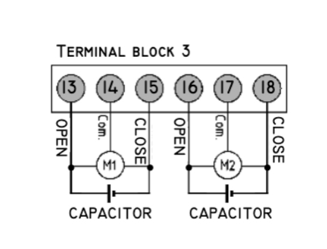
To reverse a 3-phase motor, ANY TWO LEGS are swapped and it runs the opposite direction. In this set-up you would have a "common" leg but that is a bad use of the word "common." I think, for this setup, it is just the leg that is NOT switched when the motor is reversed. --- looking at the diagram, this looks like what they are doing.

Assuming this is the case, then you would be best served to to get what is called a "variable frequency drive" (also called a "VFD") and use the arduino to control it (VFD must be capable of being externally controlled -- the inexpensive ones are ONLY controlled by their own buttons). See the one that would work for this project here, assuming your motors are less than 2HP (1.5kW) each:
Variable Frequency Drive, or "VFD"

The above is "programmable" and will accept external control. You need one that will allow you to attach an "external switch" or potentiometer - this is VERY common in the industrial world, you just need to know what VFD to look for.

I don't want to give a bunch of USELESS information if your motors are NOT 3-phase, but if they are - your solution will cost $200-$300. I'll be happy to help explain the use of this "Variable Frequency Drive" and there is MUCH information on the internet about using an arduino to control a VFD, but...

I need to know if these are 3-phase motors. The "VFD" CAN have single-phase input and 3-phase output to the motors, so if your gate is attached to "single-phase" the original controller may have been using this conversion method already -- the gates may be less expensive to manufacture this way because 3-phase motors are generally less expensive and easier to control than single-phase motors.

You can use just one VFD to control both motors - as long as they are doing the same thing and in your case, it looks like they are.

edit: spelling

These are the specs written on the motors. I will do my best to find out the whole schema of the current system.

There is a broad explanation of how the current system works in this manual.

Hi,

Not quite, they are 2phase motors.

Using this diag,
42055CC4-CCF5-4DE3-B0E1-0FE6FB164E54

You supply AC Neut to pin 14, if you then supply AC Active to pin 13, the left coil is in phase with the mains, but the right coil, supplied by pin15 receives current phase shifted by the capacitor.
And so rotates say CW.

You supply AC Neut to pin 14, if you then supply AC Active to pin 15, the right coil is in phase with the mains, but the left coil, supplied by pin13 receives current phase shifted by the capacitor.
And so rotates say CCW.

What you must realise is that pin 13 or pin 14 when not connected directly to active is still every much alive due to the capacitor.

Single Phase Motor Windings
I hope that explains it.
Anyone feel free to add.

Tom... :smiley: :+1: :coffee: :australia:

1 Like

My Italian is not too good, but I can understand all of the information and it does NOT say if it is single-phase or 3-phase.

You may need to talk to someone at the company to find out.

That was my only other thought, but I've never seen a 2-phase motor with only 3 wires, so I naturally assumed 3-phase. I've seen 4-wire, 6-wire and 8-wire... and thinking logically, if there is a 6-wire, there could be a 3-wire 2-phase motor.

Questions:

  1. can you get a 2-phase AC motor?? It seems simple, but I've never seen it. Or,

  2. Is this what is called a "servo" motor on the industrial side? I have never worked with them, only DC "steppers"