I’ve been working on designing and testing my PCB, making some adjustments along the way after encountering a few issues (and even burning a few boards!).
I’m hoping this version will finally work as intended, but I’d greatly appreciate it if you could take a look at my schematic and provide any feedback. If you notice anything wrong or think there’s room for improvement, your input would mean a lot to me!
Thank you for your message and your valuable comments.
Regarding the resistors, I noticed that many Arduino schematics I find online
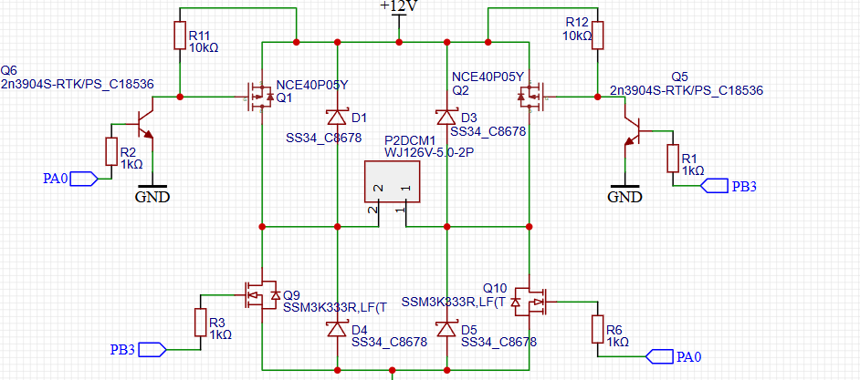
include resistors for buttons, but I understand they may not be necessary for the STM32. I’ve also updated all the MOSFETs to models with at least a 20V Vgs rating, so I hope this setup will work as expected.
Once again, I sincerely appreciate your feedback and guidance.
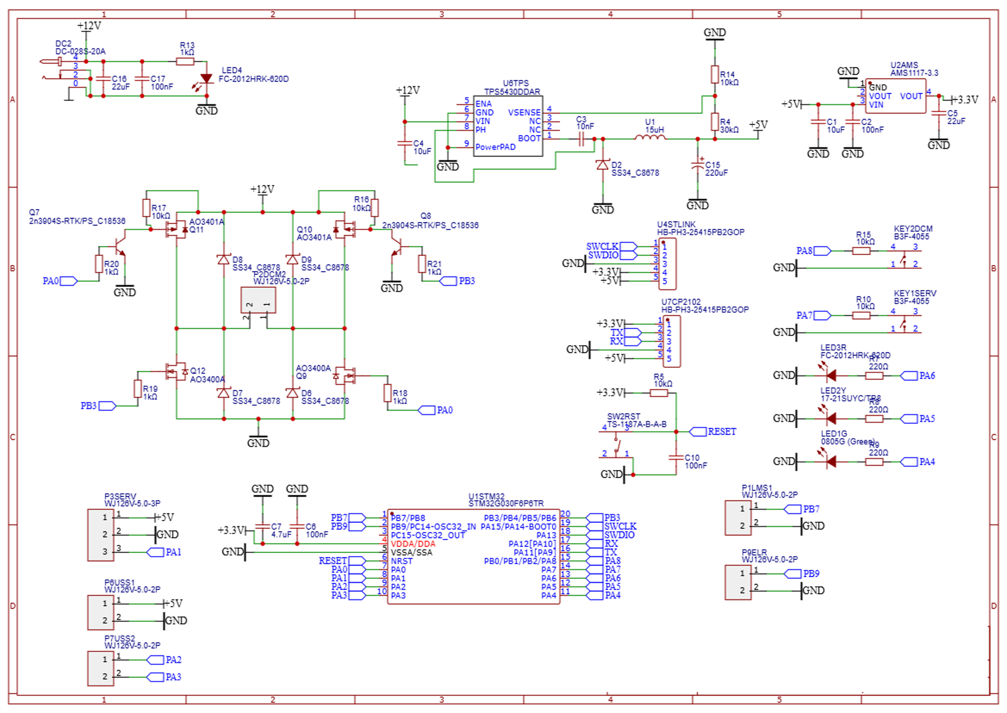
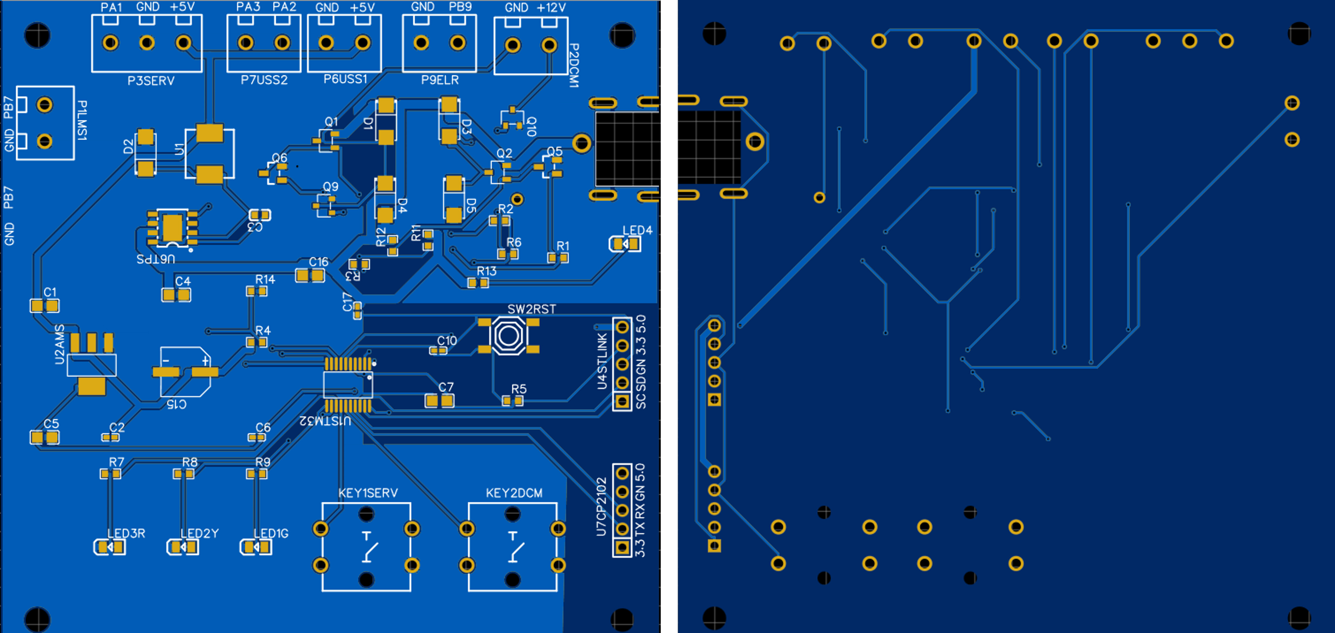
I'm designing my first fully functioning PCB and would greatly appreciate your help reviewing my PCB layout. This board is based on the STM32 microcontroller and includes buttons, LEDs, motor drivers and so on as you can see. I'm hoping to catch any potential issues before moving to production, as this is an important step for me, and thank you so much for your feedback in advance!!
mounting holes should be connected to ground (via).
increase the distance between tracks. traces close to vias/pads.
fill/polygon should be connected to ground.
use thermal relief pads.
About the use and connection, it would be desirable to have all connectors placed by 'type'. You are using 5 times the same connectors, that might be problematic.
I dont get why you have connectors by mcu port name. I would add a label (X axis, or somthing like that).
Also, motor connectors are weird. Some have ground+port, some have 2 ports. You even added labels where there are no connectors. PSUSS2? P9ELR? What is that?
I would change the position of all those connectors. And make all those connectors different. Or at least use a usefull label .
Also, key2 is too close to the pin connector, make you sure you can press the buttom without damaging the conector.
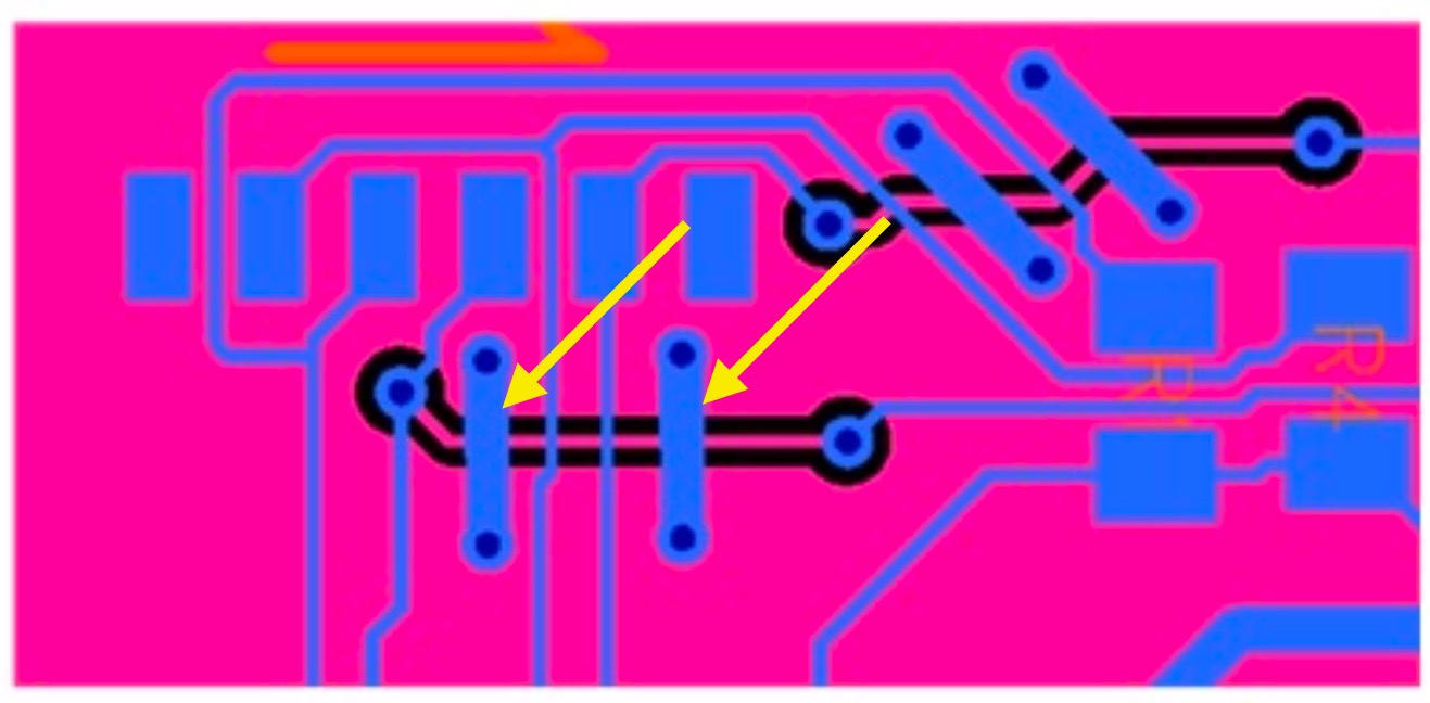
Your cross-unders are very long. Try harder to get them on the top.
Add top straps for return current over these gaps.
Remove the component side GND pour and add it to the bottom side.
You don't need the resistance R5. The STM32G030F6 datasheet (page 64-65) shows that NRST pin has a internal pull-up resistor. Only connect the capacitor and the push button.
According to TPS5430 datasheet (page 17), they mention that
For any TPS5430 design, start with an R1 value of 10 kΩ. R2 is then 3.24 kΩ.
So I would choose R4 = 10k and R14 = 3.24k
For the U4STLINK connector I would add the NRST pin instead the +5V. Which STLINK debugger-programmer are you using?
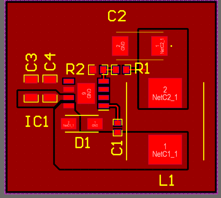
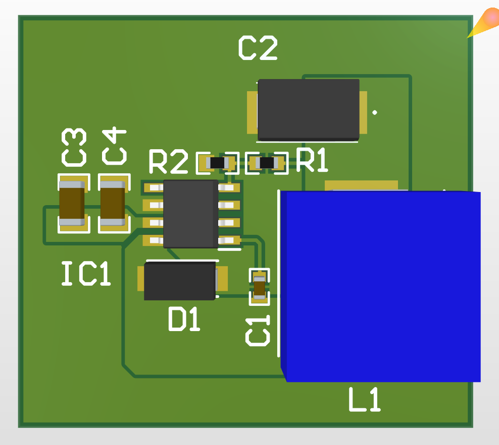
For the step down converter I would use this design
Your two or more topics on the same or similar subject have been merged.
Please do not duplicate your questions as doing so wastes the time and effort of the volunteers trying to help you as they are then answering the same thing in different places.
Please create one topic only for your question and choose the forum category carefully. If you have multiple questions about the same project then please ask your questions in the one topic as the answers to one question provide useful context for the others, and also you won’t have to keep explaining your project repeatedly.
Repeated duplicate posting could result in a temporary or permanent ban from the forum.
Could you take a few moments to Learn How To Use The Forum
It will help you get the best out of the forum in the future.
About your comment on "Key2 being too close to the pin connector," did you mean the button is too close to the U7CP2102 pin header? If so, how far apart would you recommend they be?
Once again, I truly appreciate your comments and look forward to hearing your thoughts.
I see that the STM32 has a 40k internal resistor, so it doesn’t make much sense to keep R5 as a backup either. I’ll remove it.
I initially thought a 30k resistor (more readily available) might work instead of 3.24k, but I realize I also had them swapped. I’ll update R4 to 10k and R14 to 3.24k as recommended in the TPS5430 datasheet.
For the U4STLINK connector, I’ll add another pin for NRST while keeping the +5V as an optional backup.
For the step-down converter design, I’ll review your suggestion. Do you think it might cause issues with the existing layout?
Thank you for your feedback!
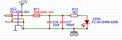
I’ve added a resettable fuse (SMD500L-16V: datasheet link) close to the barrel jack. I hope this should work well for the H-bridge as well.