Resistor ladder "emulation" ?

Hi,

I have a steering wheel control that I need to control with an Arduino. Coding is not an issue but I am wondering what is the best way to "inject" keypress into the Instrument Cluster ADC 5V signal.

Any ways to keep the steering buttons working at the same time (must not affect line resistance) ?

Digipot? DAC ?

Thanks!
Laurent

Also, I've attached the image as a file so you can download the better sized image.

Not really sure what you are talking about here or what you are trying to achieve. Is this a real car, an RC model car, a PC racing simulator set-up? What task do you want an Arduino to perform? Mimicking key presses from those 5 switches near the top-right of your diagram? What voltages are in those wires?

My best guess without further clarification would be to use opto-isolators. Duplicate the 5 resistor values (strange values, by the way, very precise down to 1 ohm) and mimic the switches with 5 opto-isolators driven by 5 Arduino pins.

PaulRB:
My best guess without further clarification would be to use opto-isolators.

Won't work. :cold_sweat: Opto-isolators have non-zero "on" resistance. Even 74HC4051 would not work except perhaps with carefully compensated values (its "on" resistance is already close to 68 Ω, so perhaps that would be quite easy!).
The resistor values are copied from the (SMD) resistor marking- 68 Ω, 120 Ω, 1k8, 300 Ω, 510 Ω. I suspect the "182" is an error. :roll_eyes:

A set of reed relays or signal relays could be used of course, but to do anything smarter requires reverse
engineering how the existing unit senses the resistances - with constant current? with a resistor divider?
what voltages relative to ground does it use/assume?

PaulRB:
Not really sure what you are talking about here or what you are trying to achieve. Is this a real car, an RC model car, a PC racing simulator set-up? What task do you want an Arduino to perform? Mimicking key presses from those 5 switches near the top-right of your diagram? What voltages are in those wires?

My best guess without further clarification would be to use opto-isolators. Duplicate the 5 resistor values (strange values, by the way, very precise down to 1 ohm) and mimic the switches with 5 opto-isolators driven by 5 Arduino pins.

I'm sorry if the diagrams are confusing it's the way Ford design them. The small numbers are pins numbers at the connector on the wire.

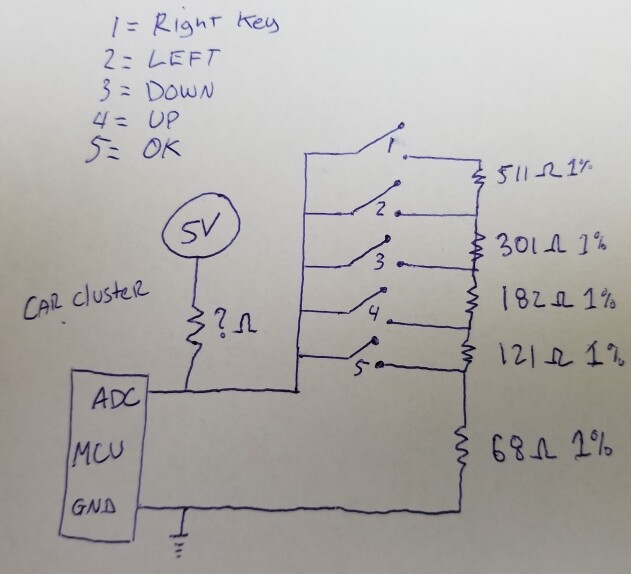
I made a quick drawing to simplify my question.

Paul__B:
The resistor values are copied from the (SMD) resistor marking- 68 Ω, 120 Ω, 1k8, 300 Ω, 510 Ω. I suspect the "182" is an error. :roll_eyes:

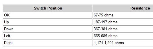
This is in fact real resistor values . It's not SMD codes. Take a look at the diagnostic page of the steering wheel controls. Ford list the resistive value of each keypress. Since it's a ladder you need to add every resistor that the switch connect. The line is always 68 ohms no matter what. Ex: Right key = 68+121+182+301+511 ohms = 1183 Ohms. This fit with the following table.

MarkT:
A set of reed relays or signal relays could be used of course, but to do anything smarter requires reverse
engineering how the existing unit senses the resistances - with constant current? with a resistor divider?
what voltages relative to ground does it use/assume?

It sense voltage variation to be read by an ADC pull up at 5V DC.

Is there any other way beside mechanical ? I need to control some menus. The only unknown variable is the pull-up resistor ohm value at the ADC. But I suspect it's more than 1k Ohm resistor otherwise that would be hard on those 1/8w resistors on the steering buttons.

resistor.jpg

Can you measure the current flowing when switch 5 is closed ? You should then be able to calculate the unknown resistor in the divider.

Edit:
Or probably easier, measure the voltage drop between the points marked ADC and GND when switch 1 is closed.

6v6gt:
Can you measure the current flowing when switch 5 is closed ? You should then be able to calculate the unknown resistor in the divider.

Edit:
Or probably easier, measure the voltage drop between the points marked ADC and GND when switch 1 is closed.

Thanks I will have a look when I'm ready to implement (tear off the steering column covers to access to connector)

Could using transistors also works or it's better to keep it isolated from the circuit with mechanical reed relay?

Would a DAC also work ? Since it's the opposite of the ADC ?

I have experience with analog capture , just not the opposite.

Thanks ! :slight_smile:

Hi,
I take it that you will only have your emulation circuit connected and the real world circuit disconnected?

As you are working with car computer and unknown currents, can I suggest KISS.
Use small relays as the switches.
That way YOUR control system is isolated from a VERY EXPENSIVE control system.

Tom.... :slight_smile:

TomGeorge:
Hi,
I take it that you will only have your emulation circuit connected and the real world circuit disconnected?

As you are working with car computer and unknown currents, can I suggest KISS.
Use small relays as the switches.
That way YOUR control system is isolated from a VERY EXPENSIVE control system.

Tom.... :slight_smile:

The circuit controlled by the Arduino will be in parallel otherwise I will loose the buttons from working on the steering.

I know my question is odd but the end result of this project is a "macro" that turn off traction control by emulating key press. Yes. it is deep in menus and take long time to reach the options in the car system menu. Why did they remove the physical Traction Control OFF switch ... I guess money saving.

I must retain the keys on the steering wheels to do other things like see Trip , odometer and fuel economy.

Reed relays will work for sure, I was just wondering what are the other possibilities. Just brainstorming!

I just feels using mechanical relays is even more a hack than it already is!

What about this schematic ? What do you think guys?

Hi,
No the two systems will interact.
When your arduino output is HIGH on say D0, that will pull the 68R HIGH, when it is LOW it will gnd the 68R.

The Arduino outputs are HIGH/5V or LOW/gnd.
You are assuming the LOW is open circuit like the switches.
OFF is not float it is a digital level, in this case gnd.

Tom... :slight_smile:
Like I said KISS.

TomGeorge:
Hi,
No the two systems will interact.
When your arduino output is HIGH on say D0, that will pull the 68R HIGH, when it is LOW it will gnd the 68R.

The Arduino outputs are HIGH/5V or LOW/gnd.
You are assuming the LOW is open circuit like the switches.
OFF is not float it is a digital level, in this case gnd.

Tom... :slight_smile:
Like I said KISS.

Wait... all GPIO can be tri-stated ... Low (Sink) High (Source, we will not use in this case) and Float/Hi-Z (Third State)

digitalWrite( D0, LOW ); Tell output low (connect resistor to ground when on output mode)
pinMode(D0, OUTPUT ); // Sink, we are connected to the resistor [Key press]
pinMode(D0, INPUT ); // Tri-State / Hi-Z / High Impedance AKA Floating (pin disconnected) [Key Released]

I'll keep in mind KISS. :slight_smile:

Laurent

So how are you going to match the Arduino supply voltage to the mcu supply voltage?

FWIW, if you persist with this folly and you’re using an Uno/nano or similar, don’t use D0 or D1. Already in use.

WattsThat:
So how are you going to match the Arduino supply voltage to the mcu supply voltage?

As long as the car ADC line stays pull-up at 5V, I don't see what's the problem. Maybe put a diode on the output of the arduino resistor ladder so it protects from any getting any backfed voltage.

Arduino is sharing the same ground as the car.

WattsThat:
FWIW, if you persist with this folly and you're using an Uno/nano or similar, don't use D0 or D1. Already in use.

Nothing foolish, I was just trying to see if any other alternative than slow bouncing emf generating clicky relays.

The outputs numbering was just for sake of simplicity.

elcouz:
Maybe put a diode on the output of the Arduino resistor ladder so it protects from any getting any backfed voltage.

You clearly do not comprehend how this resistor ladder works! :roll_eyes:

elcouz:
Nothing foolish, I was just trying to see if any other alternative than slow bouncing emf generating clicky relays.

I did explain in #2. Never mind. :grinning:

Relay bounce is irrelevant here. :astonished:

In fact, you absolutely need the relays to isolate your Arduino ground from the vehicle ground.

elcouz:
I have a steering wheel control that I need to control with an Arduino. Coding is not an issue but I am wondering what is the best way to "inject" keypress into the Instrument Cluster ADC 5V signal.

Any ways to keep the steering buttons working at the same time (must not affect line resistance) ?

Digipot? DAC ?

Hi, I have just finished testing a similar concept to what you are after in my car.

SWC (resistance ladder) -> Arduino -> Digipot -> Car Stereo

Whilst your output may not be the same as mine it sounds like the theory on capturing the analogue buttons is. What you do with that data once captured could be anything, output via OBD module for example.

I do not have a complete write up yet but here is my code, fully functioning in the car (also a Ford), with some reference links to follow for more detail until I've fully documented it.

The key thing for me was reading the buttons and capturing different 'events'. Click, Release, Double-click, Longpress. Once I sorted that part out the rest all fell into place.

AceButton was key here for me.

elcouz:
… I am wondering what is the best way to "inject" keypress into the Instrument Cluster ADC 5V signal.

Hello, Laurent. I feel you are on a generally good path. To get on the same page — the original circuit is functional with multiple input voltages on an ADC input. The input voltages are created by a series of voltage dividers. Each different input voltage is considered a request for specific action to the ECU. This is effectively no different than hundreds of other examples, from temperature thermistor dividers to light sensing photoresistor circuits, where a voltage divider provides an input voltage signal. The goal (as I understand you) is to provide both user input (through original switches) and also add the option of equivalent inputs via an Arduino.

In order to accomplish the goal, the Arduino should be able to provide the input voltage to the ECU using the original system's 5V pullup, in order to leave the original setup simultaneously functional. Your suggested drawing is the general concept of resistors, but could be accomplished several ways. Optionally could be to momentarily "cut" the switch circuit and pullup out with a FET, while simultaneously inserting the replacement signal voltage via Arduino, but timing would be important in order to avoid a circuit error (no signal) reaction in the ECU.

The original resistor ladder provided voltage division by adding resistance in-series, e.g., pressing the Down(3) switch would create a voltage divider between R1 and three resistors totaling ~371 ohms. As R1 is unknown; using an example value of R1 = 1k, the input signal voltage would be in the range of 1.353 volts. Right Key(1) would signal approximately 2.71V.

Assuming (!) that no two switches would be active simultaneously; my suggestion would be to instead switch individual resistors into the division singly, each with the total resistance of the series resistors for that switch function. For example, switch 371 ohms to ground for Down(3). The switching should be through signal devices (e.g., signal MOSFETs), as the current is too high in some cases for the Arduino pins to handle. Be sure to include the device's on-resistance (Rds(on) for FETs) to your intended resistance.

An alternative could be to use a single MOSFET as a resistor (similar to your digital resistor idea), controlled at specific levels of resistance by Arduino PWM, in order to create the equivalent required resistor effects through a single device. While simpler in concept, the hardware and tuning could be as or more complicated than simple resistors Another would be to create the required signal directly to the cut (see above) ECU pin with a PWM RC circuit outputting the voltage without resistors, e.g., 1.35V to signal for Down(3). Lots of options and just food for thought, as the requirement is simply to create a specific voltage to the ECU pin for each function; but you can see I'm leaning towards your basic concept but with single instead of series resistors.

As there is no magic in the 5V power/pullup source and no isolation should be required, the Arduino could be both powered and grounded by the system source, in order to maintain shared function and circuit completion. Any point in the vehicle that shares ground and power with the ECU (not isolated) should function. Be aware that using non-isolated remote power and ground may introduce voltage offset that could play havoc with your intended voltage control. I hope that helps in some way, and good luck!