I want to sit between them, with the following requirements:
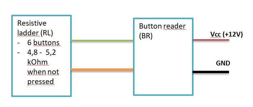
I don't want to make any assumptions about whether the second line is grounded or anything else about the BR.
Under "normal" conditions, BR should not notice my presence.
If I press a designated button (say B1) on the ladder for more than a fixed amount of time (say 2 seconds): i) BR must be 'disconnected' (as if no buttons are pressed); ii) BR must not detect the (long) press (i.e., BR must be disconnected while the press is ongoing and before it could detect the press).
When I decide to, I will reconnect BR and allow the signals to pass through.
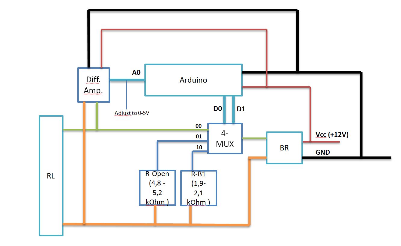
Use a Difference Amplifier to: i) Probe the signal without affecting what BR sees, and ii) Get the voltage even if a line is not grounded.
Use this algorithm:
i) Start with the MUX on the '00' channel.
ii) If a button other than B1 is pressed, do nothing.
iii) If button B1 is pressed, switch the MUX to the '01' channel and isolate BR (hoping to be fast enough to not trigger the device).
iv) If button B1 is pressed for more than 2 seconds, stay on '01'.
v) If button B1 is pressed for less than 2 seconds, switch the MUX to '10' for the duration B1 was pressed, then return to '00'.
I think that with this design there might be are a couple of pitfalls, especially with the timing to mask the B1 press.
At this point, any advice, improvements, or alternative (and better) solutions are welcome.
I considered fully isolating the two circuits and having the Arduino echoes what it detects on the input (perhaps with a digital potentiometer or a 'twin' resistive ladder), but that seems to me more fragile and less resilient, and it would require more assumptions (especially on BR).
I will assume that the ground is the reference for the buttons and that the ladder is a resistor ladder network. You can connect a voltmeter to the button signal to measure the voltage levels for different buttons. These measurements will help you determine which button is pressed. To interface with an ADC (Analog-to-Digital Converter), use a high-impedance voltage divider (several hundred kΩ) followed by a unity-gain op-amp. This setup should provide stable readings for your A/D conversion.
and 2.) Where? On BR? It triggers actions upon button release.
With the Differential Amplifier connected in parallel to the RL (green and orange), I should get a different voltage for each pressed button. So the idea is to measure it on A0, using a voltage divider to match the 0-5V range of the ADC. That way, I can make decisions to control the MUX. I think it may require debouncing and other adjustments, but it should work.
Yes, the ladder is a resistor ladder network.
I want to use a Differential Amplifier (with unitary gain) because I don't know if the ladder is grounded or not. (In fact, I plan to use it with different devices, so I can't make assumptions about that.)
My concerns are related to the timing needed to intercept B1 before the device (BR) detects it and to set the MUX accordingly, without altering the impedance that BR sees.
Anyway, other designs or ideas are welcome.
Could you explain better why it could fry? I definitely don't want that!
I think there’s a misunderstanding — the resistor ladder is already a pre-made component, so I don’t have to build it.
RL and BR are existing devices that were designed to work together.
I just want to insert myself between them.
So post a link to the data sheet for this component or at least from where you bought it.
Your diagram as you present it has 12V going into the BR then it has two outputs coming out of the BR. The green wire coming out is going to a multiplexer. What do you think 12V is going to do to a Multiplexer? And what is the orange wire going to carry?
The big problem is that what you have posted is not a schematic, it is simply a confusing, ambiguous, block diagram, not a schematic at all.
There are no proper component names.
There are no power supply lines going to the components.
There is no circuit for the differential amplifier, just a block.
There seems to be no power supply decoupling capacitors in the circuit.
That will be a good trick because then the voltage will be floating, and you can't measure a floating voltage with an A/D converter.
My confusing block diagram was meant to discuss the concept (or any viable alternatives) before diving into details.
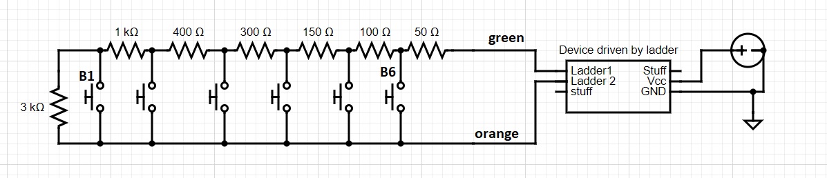
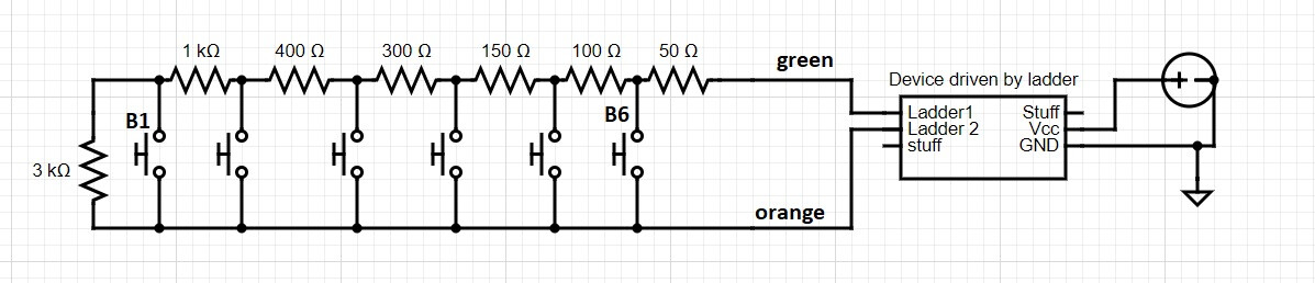
Here’s a simplified schematic (without capacitors, protection diodes, etc.).
RL and BR are simply off-the-shelf components designed to work together, connected together by two wires (green and orange lines, in my drawings). They could be, for example, buttons (RL) that move a point on a screen (BR).
RL is definitely a resistive ladder, and I can easily figure out the resistance values with a multimeter.
BR calculates the voltage between the green and orange lines, maybe with a simple voltage divider, or perhaps something more complex. I don’t want to reverse-engineer this by design, because I have to work with several BRs, and the solution should be resilient enough without needing further details on this aspect.
BRs operate at 12V, and I plan to use the Arduino’s 5V to power the MUX and as a reference for the differential amplifier.
Why are you keeping this a secrete?
Which is why I asked for the part number, or link to where you bought it. In other words what is the shelf they came from?
Normally in a resistor array all the resistors are of the same value with a common connection. Like the sort of thing you would use for multiple pull up resistors. Now in your diagram you have the resistors in the array all having different values, this is not normal. Is this part of RB and RL or are you making this ladder with your own parts? If so you need to sort out individual resistors to make sure they are accurate enough. Also those values are not very good to detect a button press, you would normally use an R/2R ladder.
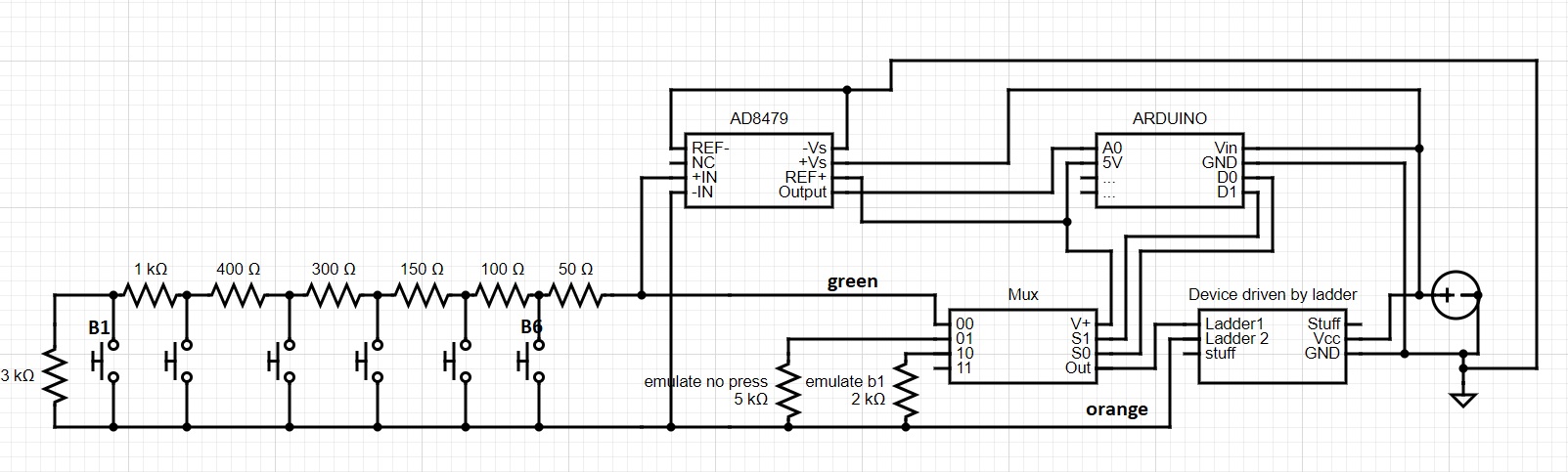
The box on the right says "Device driven by ladder". It has two power inputs a Vcc of 12 V and a ground. But it also has a Ladder1 connection, which seems to be connected to the output from a multiplexer. So this is somehow feeding into that circuit. So I can't see what this is going to do, that is how it will interact with the device driven by ladder box. This box also has enigmatic "stuff" inputs an outputs labeled.
Also the AD8479 is somewhat overkill for what you are trying to do, Click here to download the data sheet for this part
Also I am not convinced you have the wiring correct as none of the components have any pin numbers associated with them.
The problem is you know that it means but we don't. You have these devices and we don't. So if you want to communicate your ideas with others you have to explain exactly what you have and not keep secretes.
Hi Mike,
Thank you again for your time and interest.
I think there have been a lot of misunderstandings, likely due to my poor English.
If you don’t mind, I’d like to start from scratch. Before that, I want to clarify that there are no secrets here — I intentionally treated RL and BR as black boxes because that’s a requirement for this small project.
Here’s the situation:
I have a COTS device composed of:
i) a head unit (powered at 12V) and
ii) a wired remote control connected by two wires.
The remote control has been reverse-engineered (a big word to say that I looked inside and measured the resistances with a multimeter...) and it’s nothing more than a resistive ladder.
I want to create a device (based on Arduino) that I can place between the head unit (BR) and the remote (RL). This device should pass through the signals from RL to BR, until a certain event occurs (e.g., a long press on one of the remote's buttons). When that event happens, I want to isolate BR until another event occurs, after which I want to pass the signals through again.
So, I’d like to discuss the best solution to achieve this. I started with a solution I had in mind, but I’m completely open to changing my design. I’m here to gather feedback before diving into a proof of concept.
Assumptions and requirements:
I don’t want to reverse-engineer how BR calculates the voltage from the ladder. This is because I don’t want my solution to be influenced by this specific BR; I want it to work with any (well… several) devices driven by a wired remote that uses a resistive ladder. That’s why I don’t want to assume BR calculates the voltage with a ground reference.
I need to avoid influencing what BR sees, which I believe means I should avoid drawing current from the remote lines.
So, I have two DISTINCT problems to address:
Measure the voltage between the ladder pins (the orange and green lines) without affecting the original circuit. I think this is doable because it’s essentially what a multimeter does. Obviously, I need less accuracy and precision since I only have a discrete number of voltages to measure (one for each button).
Alternate between passing through signals and disconnecting RL from BR.
The resistor array I’m using for experiments is built with a different resistance value for each button. It was designed that way, implemented that way, and it works with its BR.
The multiplexer is part of my solution (so it’s not mandatory if you have better ideas)!
In my solution, the multiplexer serves as a way to select between three different states of the system:
00 - Pass through (nothing should change from schematic #1, from the BR point of view)
01 - Emulate no button press (ie., disconnect BR from RL)
10 - Emulate the press of a specific button Emulate the press of a specific button (this is needed in my algorithm to handle cases where the button - say B1 - isn’t pressed long enough, so I need to echo the press to BR).
Do you think the MUX will create a different impedance seen by BR or anything else that could interfere with how BR calculates the ladder resistance/voltage? I know the question might be difficult to answer without specific assumptions about how BR circuits work, but this is exactly the challenge I’m facing, as I have to deal with different BRs that may accomplish this task in different ways (though I suspect in 99% of cases, it will be a voltage divider with the second pin referenced to ground).
"Stuff" was just a way of saying "don't care, BR has a lot of other inputs to accomplish its task."
I only wanted to point out two information:
BR is powered at 12 volts
BR has two input pins to connect to the resistive ladder.
The other pins shouldn't affect this discussion in any way!
That’s interesting. Can you suggest some alternatives? I stopped my search when I found a differential amplifier with unitary gain. As far as I understood, it has the nice feature of scaling the output based on the reference voltage at the input, so I shouldn’t need any additional components to bring the measurement into the 0-5V range of the A0 pin.
I hope I’ve answered all your questions and concerns.
At the moment, I’m using an old car stereo (BR) I grabbed from a demolished car, along with its wired six buttons remote (RL), to run experiments. I didn’t mention this earlier because I didn’t want it to influence the design...
I want BR to be anything, as long as it’s controlled by buttons arranged in a resistive ladder and connected to it with two pins.
Well a slight step closer in that I now know that BR and RL are things from a car, and not the "off the shelf" item you said it was. But I still do not know what they are and how they work.
Sorry but you don't seem to realise that I have to know what these components are and how they work in order to understand how to interface these to your resistor ladder. If that means reverse engineering them, then that is what is needed.
I don't "do" automotive work, so I do not understand your jargon. Maybe someone who does this sort of thing might come along and be able to help. Maybe you can change the title of this thread to indicate this is an automotive problem. Please don't start a new thread, that is against the forum rules. Also note that the datasheet for the processor in the Arduino says it should not be used in automotive or health safety applications.
Any operational amplifier can be made into a unitary gain amplifier by connecting the output to the -ve input.
Hi Mike,
thank you for your time again.
Here we are.
That’s exactly why I didn’t want to mention the actual devices I’m using. This has nothing to do with "automotive." We got sidetracked just because I mentioned "car stereo," but there's nothing special about this type of device. Again, I just want to probe a voltage (between orange and green) in a way that doesn’t affect the system and isolate a component from the ladder when an event occurs.
But I need to probe this voltage between orange and green, and I think with an operational amplifier (and not a differential amplifier), I would have to reference each ladder line to ground, which isn’t what I want.
By the way, after retyping my solution a few more times, I found a big logical mistake—so it doesn’t work, and I need viable alternatives. Putting the MUX on 01 and 10 will also isolate the ladder, which would leave it without voltage, meaning I can't read anything.
I started this discussion to uncover these "high-level" pitfalls and errors rather than discuss the final implementation details.
I think that with any opamp configured as differential amplifier (or not) you can just use one of the lines as GND reference, provided that the voltage range is inside the opamp rails.
But I don't understand where does the voltage come in the resistors ladder. Between green and orange you can measure resistance, not voltage:
The device (BR) applies a voltage to the ladder and measures the resistance using something like a voltage divider to determine if and which button is pressed. I can easily read the voltage with a multimeter when BR is running.
Ok, then put a voltage divider to reduce the voltage range (if needed), use the lower side as GND reference and read the voltage of the other side with the MCU ADC.
On the other side maybe you don't need a resistor ladder, just put the same voltage than the device expects.
But you are not showing how the device apply a voltage to the resistor ladder. There should be another wire.
You can keep the same system, or replace/bypass it as well and apply your own voltage. But I don't know how is the setup.
An operational amplifier is a differential amplifier. It has two inputs + and -. It amplifies the difference between those two inputs. That is all your chosen amplifier does only it has a stupidly high maximum differential voltage.
You still do not understand what I mean. And this is getting very frustrating.
How on Earth do you expect anyone to tell you how to interface a devise when you do not fully describe what this device is? It is impossible.
With electronics you can't talk about generalises without understanding the specific. And as you will not, or can not, describe these things then I can not, with the best will in the world, help.