I'm relatively new to building project from scratch so I don't know all the best practices. I want to minimize and consolidate the project hardware by removing the breadboard. At this point the resistors are the only thing connected to it.
You could install headers on those signals then plug DuPont connectors onto the headers.
If you need the resistors, cut each wire going to this connector, solder a resistor at the cut, heat shrink the resistor and soldered connections. (there would be one resistor in line with each wire)
Do you think the resistor size really matters, since we're only measuring relative resistance?
They're pulldown resistors. Their values should really be selected to suit the velostat resistance, to give good sensitivity.
Before building the mat, you could do a test with a scrap of velostat and two small pieces of copper foil, with 5V applied to one piece of copper and the other side connected to both a pulldown resistor and an analogue pin. Then choose a resistor value that gives a good voltage swing when pressure in the range that you need is applied to the mat.
(At least that's what I'd do. )
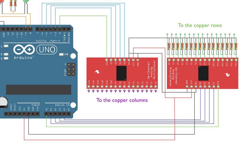
I noticed a fault in the UNO LED wiring in the Instructable. Don't copy it:-
Edit: I missed the photo you attached when I first read your opening post. You have the resistors connected wrongly. They're not supposed to be in series as you show.
As I said, they're 'pulldown' resistors, and connect from the multiplexer inputs to ground, then the ribbon cable also connects to the inputs. :-
On an aside, I think that if people are going to publish 'Fritzing' diagrams, as in this 'Destructable' 'Instructable', they should take the time to set the resistor values correctly. The instructions say 1K, but the colour-coding on the Fritzing resistors shows 220Ω.