Pulldown resistor overheating, getting fried

I recently started working with the Arduino R4 Wifi to create a component in my garage for sensing when the garage door is up or down (using 2 magnet activated door sensors, one for up, one for down).

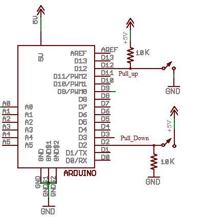
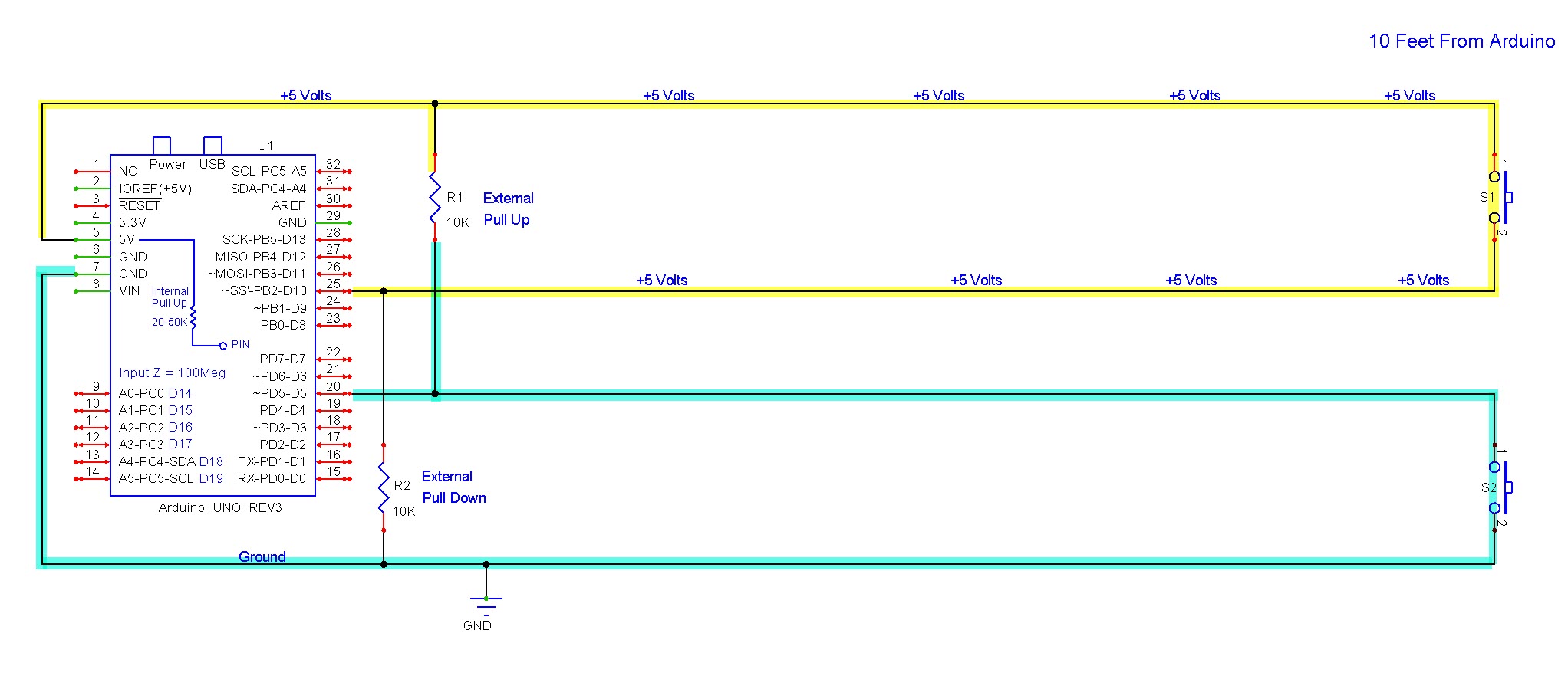
After learning the R4 doesn't have built in pull-up resistors, I implemented my own using 10k resistors, following the proper wiring from several online examples.

It was working fine, for a few days, then the door down sensor stopped working because the resistor got fried (and event melted a little of my breadboard).
Later I switched to pulldown resistors (and adjusted my logic), and the same thing happened.

TL;DR;
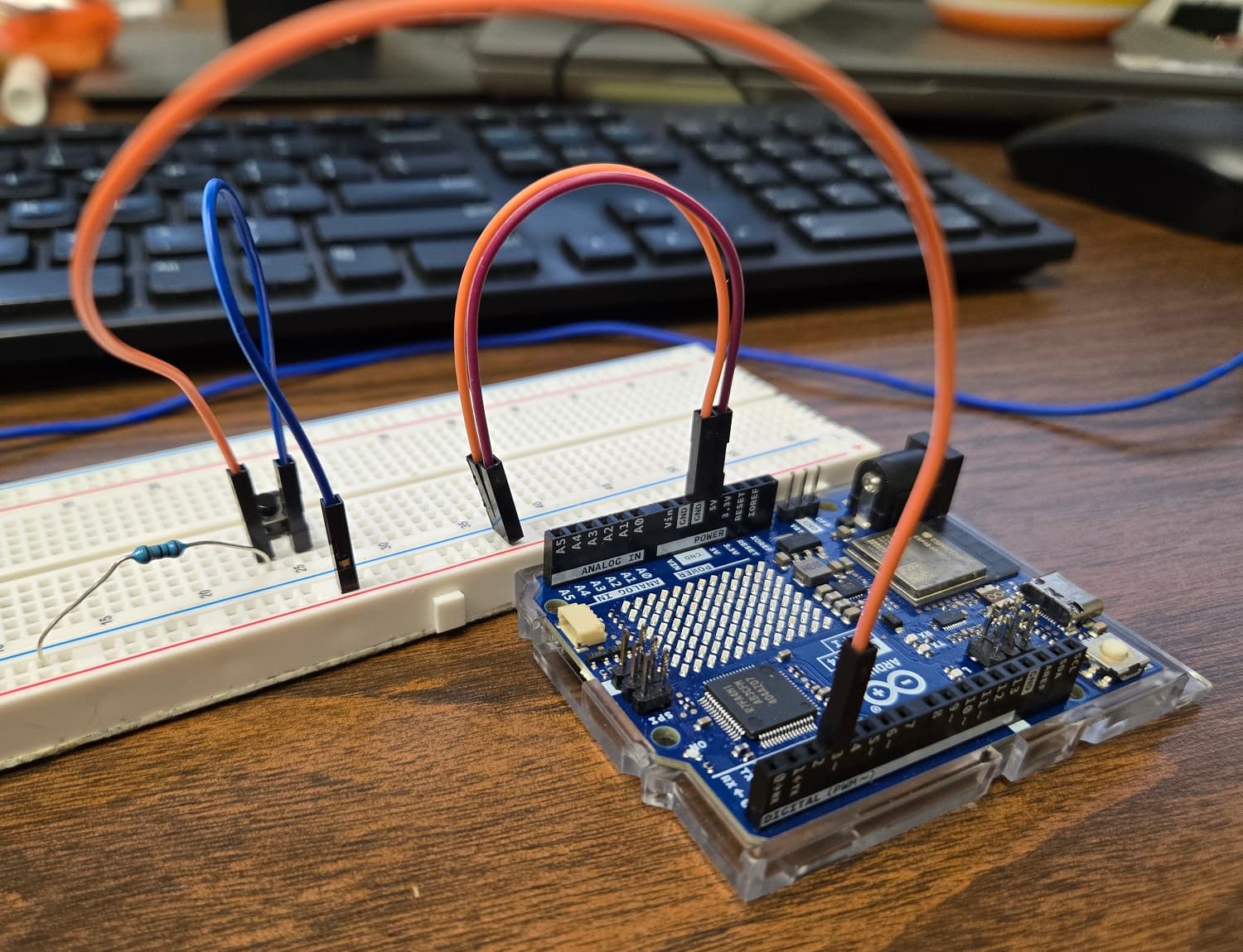
Eventually I created this simple wiring below (using 10K resistor), and used the provided Example "Button" sketch, but modified it to not use the built in pullup resistor .
Pictures:


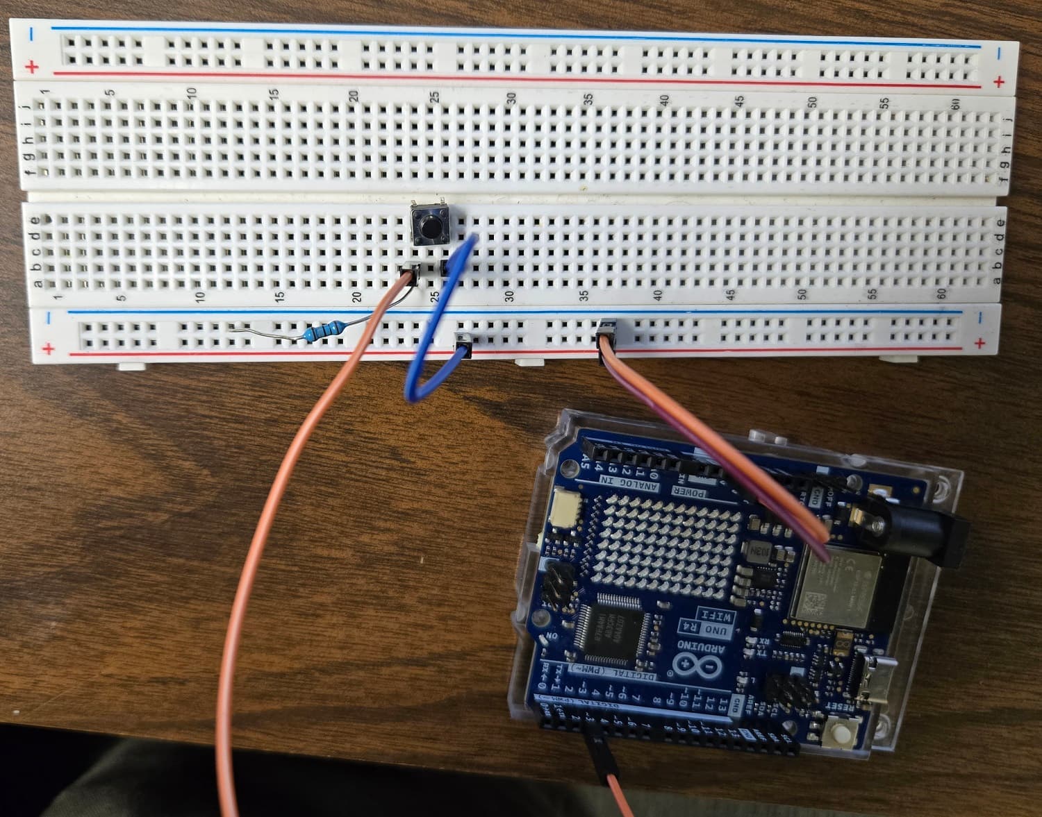
When I hold the button down, the resistor gets VERY hot. When I put a volt meter between the resistor and ground, I see the volts go up to 5v and amps at .3 when the button is closed.

If I understand wattage correctly, that's 5 x 0.3 = 1.5 watts. My resistors are the ones that comes with the ELEGOO Mega Starter Kit, so I don't know the watt rating.

So is my solution to buy 2 watt resistors? Or can use multiple ones in parallel?
Or would just a higher rated resistor work (like 1M)?
I just see so many examples using 10k, I'm surprised mine got burnt up like this.

Hi, @runzwitscissors

Use your meter to measure the resistance of your resistor.

That resistor should have a red band or orange band on it depending on if it is a 4 or 5 band colour code.

5V across 10k == 5 / 10000 = 0.5 mA.
Power dissipated P = V x I = 5 x 0.0005 = 0.0025 Watts

Your resistor;

5V 0.3 A == R = V / I = 5 /0 .3 = 16R. nearest prefered value 15R

15R brown/green/black

Tom.. :smiley: :+1: :coffee: :australia:

1 Like

Besides it seems to me that this resistor is not 10K (Maybe 10 or 1 Ohms), it seems that what is connected as pull_down and not as pull_up.

Where did you learn that?

Pull-up pull-down

image

GREETINGS ALL!
Wow, you all are quick. Looks like I need to reply quickly here.

First, YES, it looks like I was using 10 and not 10K resistors! Wow, sorry I missed that one.

Second, for some reason I thought I read that the UNO R4 WIFI did not have built-in pullup resistors. I guess they do.

Ok, good to know. Thank you all!!

1 Like
  • We suggest you wire simple switches as S3 below (internal pull-up enabled), all controllers I’ve seen have pull-up resistors.

Hi @LarryD

Could you please explain what the issue with S1/R4 is?

  • let’s say we have circuit S1.
    Let’s say the switch is 10 feet from the Arduino.
    This means we are taking the +5v supply line out 10 feet and 10 feet back.
    5v is now extended 20 feet with the potential of it coming in contact with things that can go pop if there was ever a short circuit on the cable.
    Also, sending 5v out on a 20 foot wire allows inductive coupling to noise sources that can cause serious problems back at the Arduino.
  • If we are using S2, the R1 pull-up is back at the Arduino, the switch is 10 feet away as before.
    If there was a short on the 10 feet of wire, the external pull-up (R1) limits the short circuit current.

3 Likes

This topic was automatically closed 180 days after the last reply. New replies are no longer allowed.