Reverse Engineering 2.4G RF Remote

So I have this Opple LED light that comes with a remote control. It's using 2.4Ghz RF, so decoding using normal 433Mhz module is not possible.

I've hacked open the remote control (I have many of them). Referring to the attached image, it turns out that I just had to short the outer ring (pointed with green arrow) with the inner dot (pointed with red arrow) to make it "press" the button.

I suppose I can use some kind of BJT to make an electronic switch, that will do a temporary short circuit to connect the ring and the dot? If my assumption is correct, can any one share a diagram of how to wire the BJT?

Of course, this will be an Arduino solution. That means I am looking for ways to use Arduino to make an electronic switch.

Any ideas or insights? Thank you all in advance! :slight_smile:

So what you actually want to do is to modify the existing remote instead of reverse engineering it! That actually makes it simpler at a conceptual level (but it may be more difficult in a hardware sense because you have to live with the existing PCB and housing).

Your idea of using a BJT (or, as I would suggest, a small signal MOSFET, but either will likely work) should work, but it depends a bit on how the pads are actually connected. It's common for input buttons to draw a processor pin to GND, but this is not always the case; some engineers may choose to actually pull a signal line high to Vdd or something derived from that to give an input.

Assuming that they do it the 'normal' way here (i.e. shorting an input pin to GND), the schematic would be fairly simple; you'd just take a BJT and connect the emitter to GND of the target PCB and the collector to the input pin. Make sure to include a resistor (something like 10k should work OK) between your Arduino output pin and the base of the transistor. Or, when using a mosfet, you'd tie its drain to the input pin on the remote PCB and its source to GND. A gate resistor is commonly include similar to the base resistor when using a BJT (something like 1k would be OK for this; it's not very critical).
In either case (BJT or MOSFET), make sure to tie GND of your Arduino to GND of your remote PCB.

But, remember, the above is under the assumption that the button switching occurs by shorting a pin to GND. We have not verified that yet!

But, remember, the above is under the assumption that the button switching occurs by shorting a pin to GND. We have not verified that yet!

Thanks for the idea! Is there an easy way to tell (perhaps using multi-meter) that it's shorting to GND?

Yes, find GND on your remote PCB and check if it has continuity with either the outside or the inside ring of the button. Odds are the layout is the same for each button.

Thanks for the insights! So I've basically confirmed the ring is positive. I'll see if I can draft up a circuit that does not burn anything. Haha. :slight_smile:

So the ring connects to the Vdd of the circuit? That makes things a little different as you'd have to use a PNP BJT or a P-channel MOSFET instead of a more usual NPN/NMOS.

Can you confirm for me? I am attaching the pictures here. In the picture, R = Ring, D = Dot.

And in case you need to see the whole board.

Thank you again for the help! :slight_smile:

First, be careful. I wouldn't hack or hijack a remote control unless I had or was sure I could obtain a replacement unit. If nothing else, Murphy's Law might mean you would have less probability of breaking it as you experimented.

Ring is positive

is not proof they are all

connected to Vdd

the OP could be reading pulled high rings?

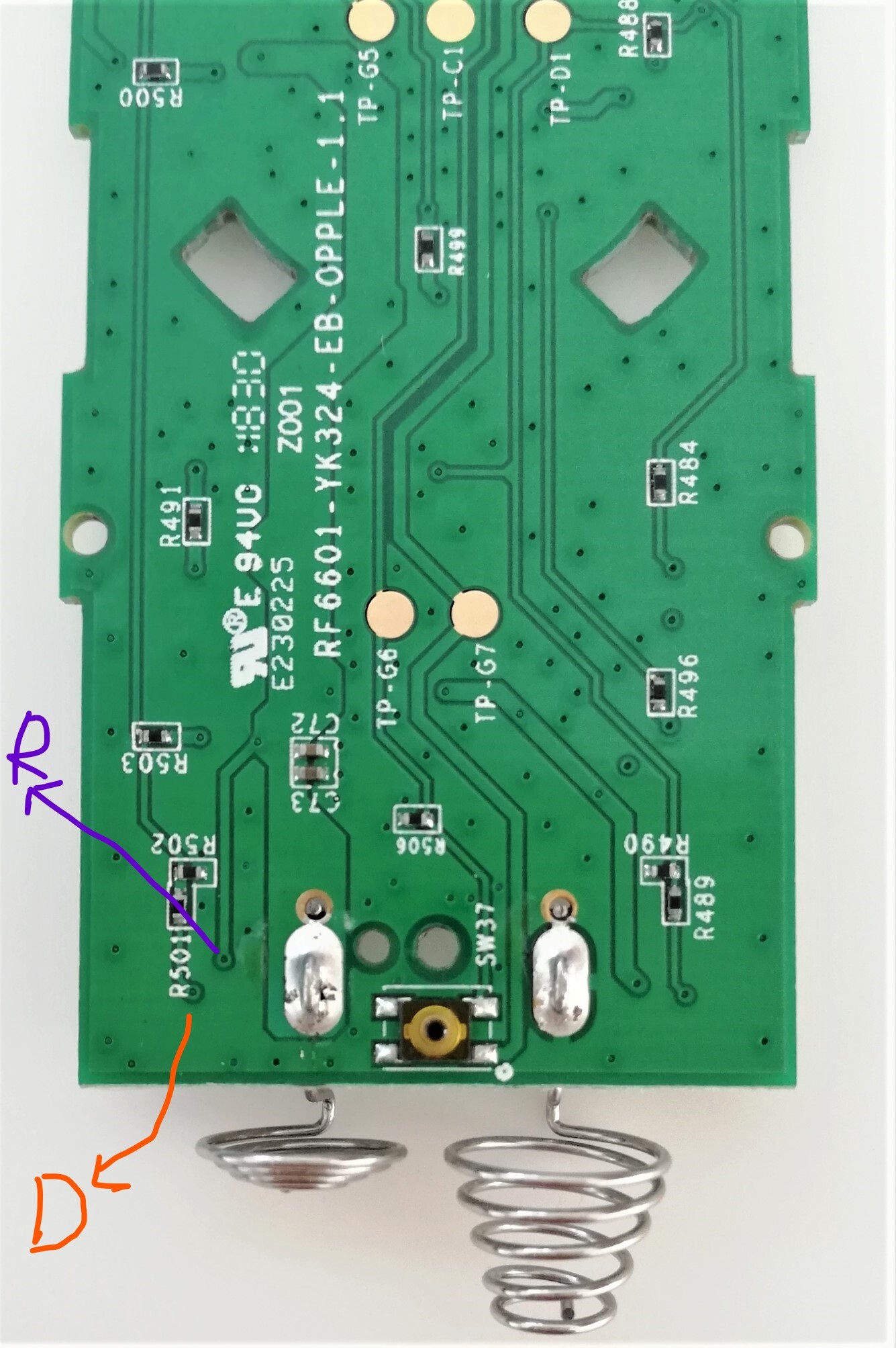
What are the dots measuring?

Are these button switches never a scanned matrix in this kind of remote?

Low(er) knowledge solutions:

Use a small relay for each switch you want to press. That's isolated tots and lets one "press" the button by operating the NO contacts on the relay.

Or

Use a CMOS switch, like in a 4066, just like you would have done with the relay. Power the CMOS IC with the remote Vdd/Vss, common ground to the Arduino and deal with the logic level translation necessary to close the CMOS switch using an Arduino output signal.

I never tried the CMOS thing. Just now I cannot google up anyone who has, but always had in mind to research or just try it as it seems entirely plausible.

I look forward to the heavies' opinions on the CMOS idea.

Both methods should work no matter the real switches pull high, low or are matrix scanned.

One problem with of all methods, to varying degrees, is the mechanical concept; seems unlikely that you could end up with something yet handheld w/o some clever cramming it all in there... obvsly relays are out if that is a desired goal.

BTW I feel there is enough "reverse engineering" in doing this that the OP would def qualify for the merit badge, at least the first level. :wink:

HTH

a7

This question pops up several times a year.
Stock answer:
Operating a remote control button is commonly done with an opto coupler.
Transistor across the button (polarity is important).
Opto LED (with current limiting resistor) driven by an Arduino.
Opto coupler must be inside the remote.
Leo..

First of all, thank you very much for the idea! I still need time to digest your text, as I am really an electronic novice.

I have 6 of them, and all 6 of my lights can share the same remote. So hacking one won't do me much damage. :slight_smile:

No, I do not want to handhold it. If it's eventually successful, the 'device' will be put inside a wooden case.

The reason I want to do all these is that I want to convert my light into smart light, controllable by Alexa.

As a software programmer, the Alexa part is easily solved. But the electronics part really is not my realm. :slight_smile:

OK, I have no idea what is an Opto Coupler, but thank you for your idea! I am now researching along this path and I'll see how far I can get. :slight_smile:

Basically an electronic switch that electrically isolates the two devices with light.
The PC817 is common. You can find one on every opto isolated relay module.
Leo..

Thanks for the useful insights! :slight_smile:

Dealing with the individual buttons is not the simplest solution. You have 18 of them. On the other side you have a chip with 16 pins. There are at least two power, 2 crystal and one antenna. That leaves a maximum of 13 I/Os. To scan 18 buttons, you need at 4x5 or 3x6 lines if it is done digitally but maybe they used the resistors do something smarter to save pins.

Do you have an oscilloscope?

  • there should be 3 or 4 pins that create pulses at the scanning frequency

  • there should be 5 or 6 lines without a signal unless you push a button

  • if you can get the signals, it would certainly provide some parameters that may lead to a simpler solution than having 18 transistors pushing button

  • it looks like the antenna is the top left pin

  • ground seems to be the pin next to the antenna

  • the crystal is on the right side (looks like 2nd and 3rd from the top)

This

gets around to a nifty solution for nijacking a matrix keypad, I think that is what @Klaus_K is getting at.

You still pretending the switch, just a bit more less dumbly.

a7