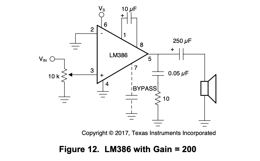
Right now I'm using a simple low-pass filter of resistors in series and capacitors in parallel to change the square wave of the tone function into a sine wave. Afterwards I have a simple amp using the LM386. For the amp I'm just following the suggested circuit in the LM386 datasheet:
While I think the low-pass filter can be placed into this 2N2222 circuit so long as I'm not using electrolytic capacitors, I want to be able to use electrolytic capacitors. Polarity also pretty clearly matters on that LM386 circuit.
I want to invert the voltage for better quality sound. The tone function is fine for driving a piezo buzzer, but I assume it's not the best for controlling a real speaker driven by induction. Am I just wrong---is it fine to drive a speaker with the tone function?
Is my analysis correct that I can't combine these three circuits (the 2N2222 inverter, low-pass filter with electrolytic capacitors, and the LM386 amp) together?
Is there any way at all to combine an inverter, low-pass filter, and amp to get the tone function to produce an amplified alternating voltage sine wave?
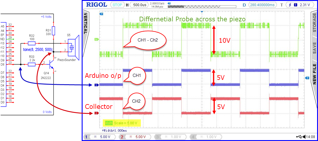
Tracing your signal with an oscilloscope would let you see where the problems occur.
Using a low pass filter on a square wave just chops off the sharp corners of a square wave. The fundamental is still there. A scope would let you adjust the resistor/capacitor values to better get the signal you want.
Paul
You need an amplifier of some sort to drive a speaker. A naked Arduino pin cannot do it.
If you want a louder signal than the LM386 can produce, use a more powerful audio amplifier, with a separate power supply. You do NOT need a "polarity reversing" circuit.
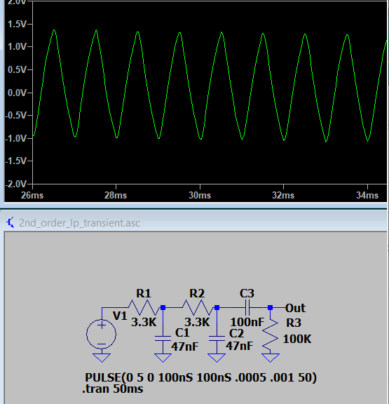
To obtain a more pure sine wave from the tone pin, use a better filter (2nd or 3rd order low pass), and a series capacitor to remove the DC component. Very important: use an appropriate cutoff frequency.
Something like this, but with R1 and R2 higher (suggest 3.3K):
There are standard online designers for low-pass filters. You choose the "order" of the filter (how steeply it cuts off the sound), the type of filter (there are different types with slightly different characteristics, but just choose Butterworth), and the cut-off frequency, and the designer will create a schematic for you with component values. Do a Google search - there are several good ones around.
That only works for digital signals - for an analog signal you'd use two LM386's driven in antiphase, with the speaker bridged between the two
outputs (aka bridged mode amplifier).
To generate antiphase signal pair you normally use an opamp inverting
amplifier with a gain of -1. That would be after the filter and before both
LM386's.
However these days that's complete overkill, as the 5V class-D amp chips like
the PAM8403 already are bridged mode and solve the problem in one module.
