I have a 24V RGB lighting strip, and I'm trying to control it using an ESP8266 Arduino board (WeMos D1 mini).
In order to reduce the number of parallel power connections I must run, I was hoping I could supply both the RGB strip as well as the board off a single conductor pair, and use a step down voltage regulator to reduce the 24V down to the 5V needed for the board, like this:

Anything wrong with this concept? It seemed to work just fine on the breadboard. Then I tried to solder it on a perf board. The first one I made worked great, and then the next 5 in a row all failed, and with the exact same failure characteristics. But I can't figure out what I'm doing wrong...
FYI, I'm a complete beginner to electronics / Arduino.
The issue is the RGB strip simply does not light up. Using an oscilloscope, I can see the voltage fluctuate between 0V and 3.3V on the data line, so it's not like it's completely flat at 0V as if I had a short. However, compared to a working unit, the faulty units all exhibit the same characteristic where the data signal is highly compressed time-wise.
Here is the scope display for the working units (from breadboard, and the 1 working unit I made with the perf board, they all look similar):
And then here is what the scope display looks like for all the faulty units:
Note the axes are identical - same sampling rate, same voltage. Like I said, I'm brand new to electronics, so maybe I'm misinterpreting what the scope is saying - but it looks to me like the signal is still there, but highly compressed time wise. Why would that be, though?
Here are the components I'm using:
Board:
WeMos D1 mini (ESP8266)
Step-down converter:
Pololu 5V, 2.5A Step-Down Voltage Regulator D24V22F5
RGB strip:
WS2814F (24 Volt Addressable RGBW LED COB Light Strip Ultra Bright 784LEDs/m)
Links to all of the above (posting as a single link, since I'm limited to 4 links in a post as a new user):
Finally, here is the code I'm running. This is just for reference, as I don't think it's a coding issue in this case. Most of the code is related to being able to perform OTA updates over WiFi, debugging via WebSerial, and being able to start/stop the animation via HTTP POST requests:
Then here is what the soldered unit looks like - front:
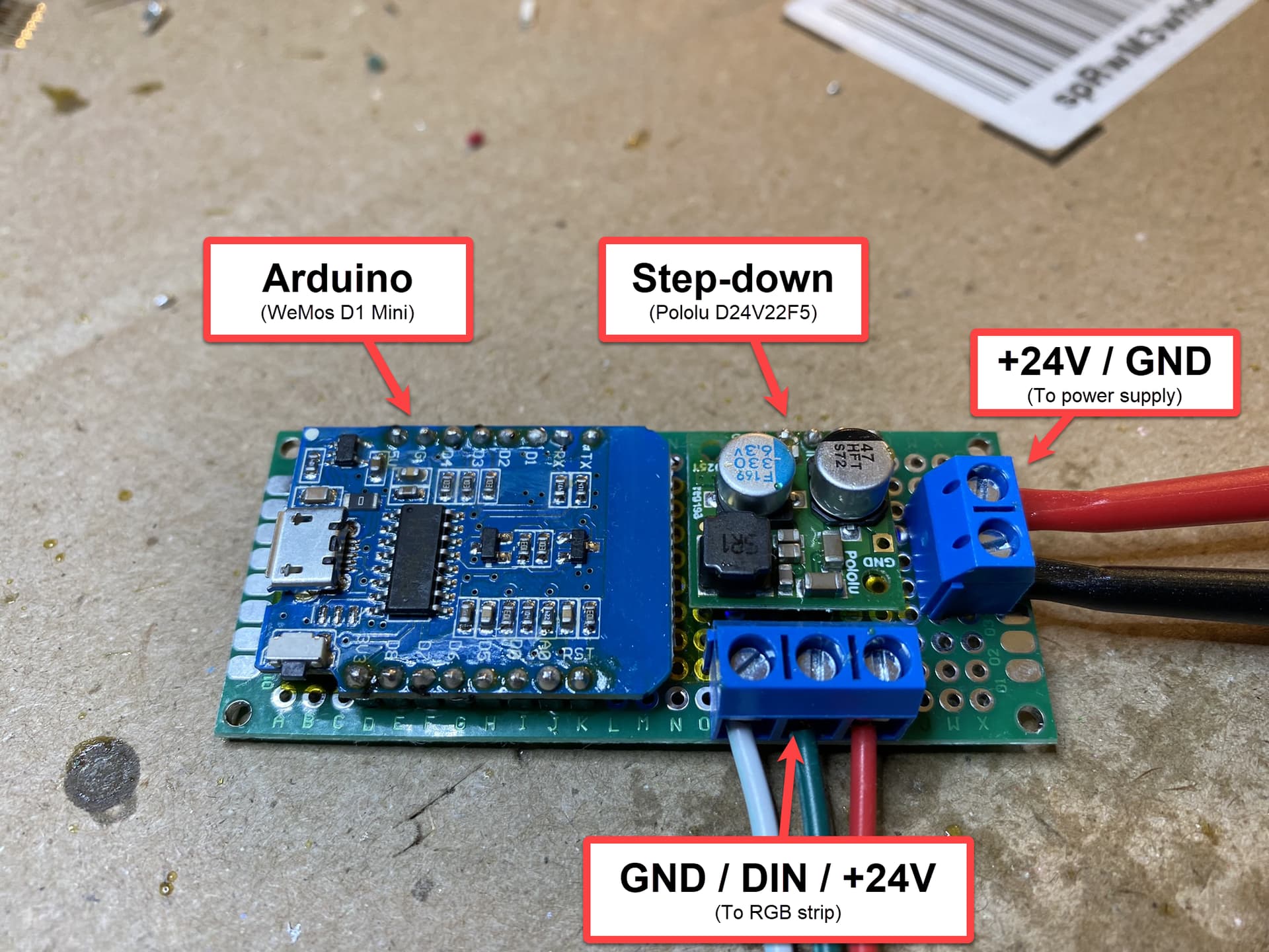
Back:

I'm powering it with a variable power supply for now, and verified it's supplying the correct voltage (24V).
Where I'm measuring the signal for the scope is at the screw terminals for the DIN and GND lines for the RGB strip, since they're easy to access.
Any idea what I might be doing wrong? I assume it must be my sloppy soldering technique, if it worked fine on the breadboard? Or is the whole concept flawed in some way?