I have used RGB led strips, and controlled them with PWM and MOSFET before. For them I have used a 12V DC PSU because the measured voltage from the controller box that came with them supplied 12V for the whole led strip.
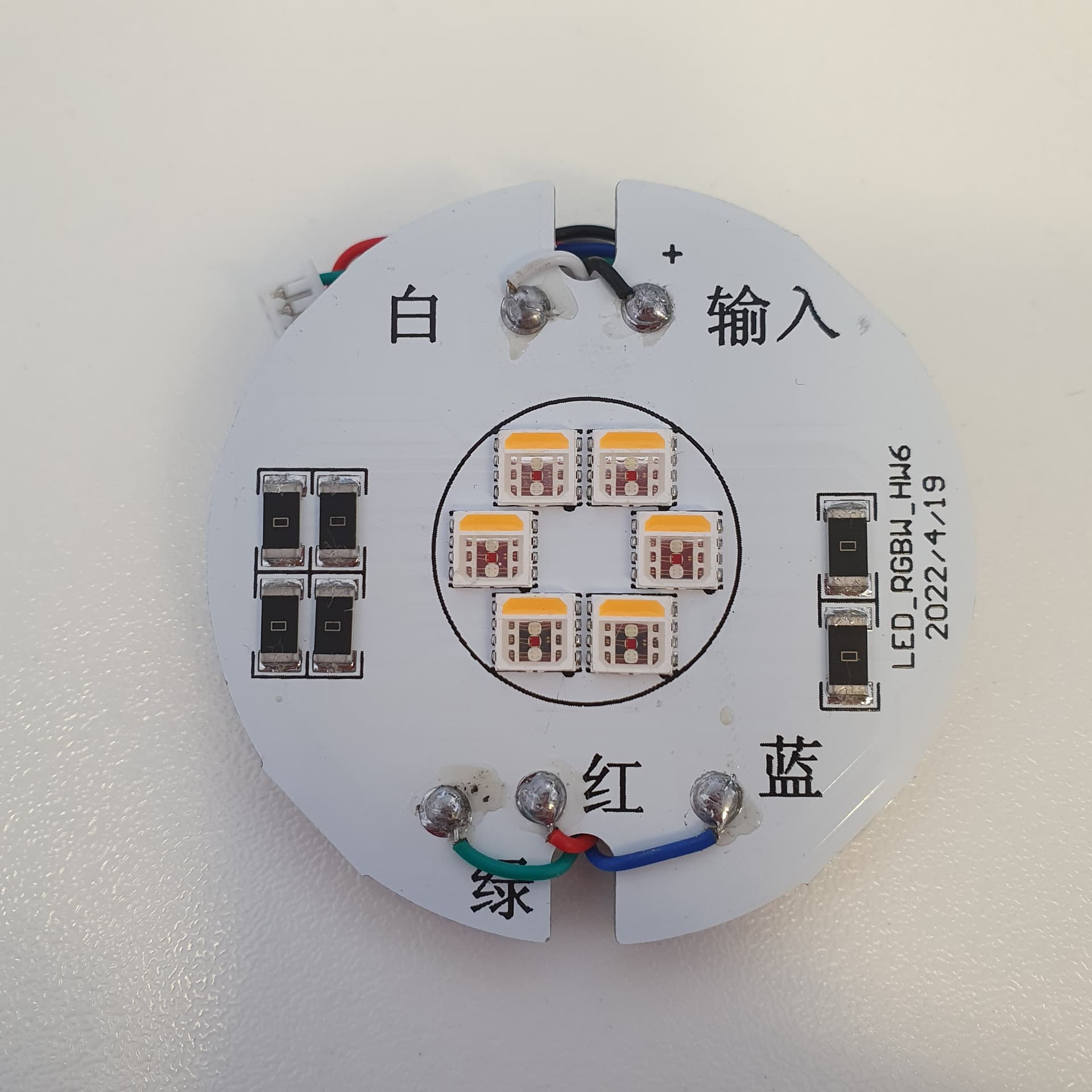
Now I am trying to control these RGBW Spotlight from Sunvie. Each Spotlight has a built in PCB and 6 x RGBW leds. The circuit can be supplied with 12-24 V AC or DC.
When I measure the voltage going through the wires for each color when only that color is on full, it's only 6,25 V DC.
Does this mean I should only supply the MOSFET with about 6V?
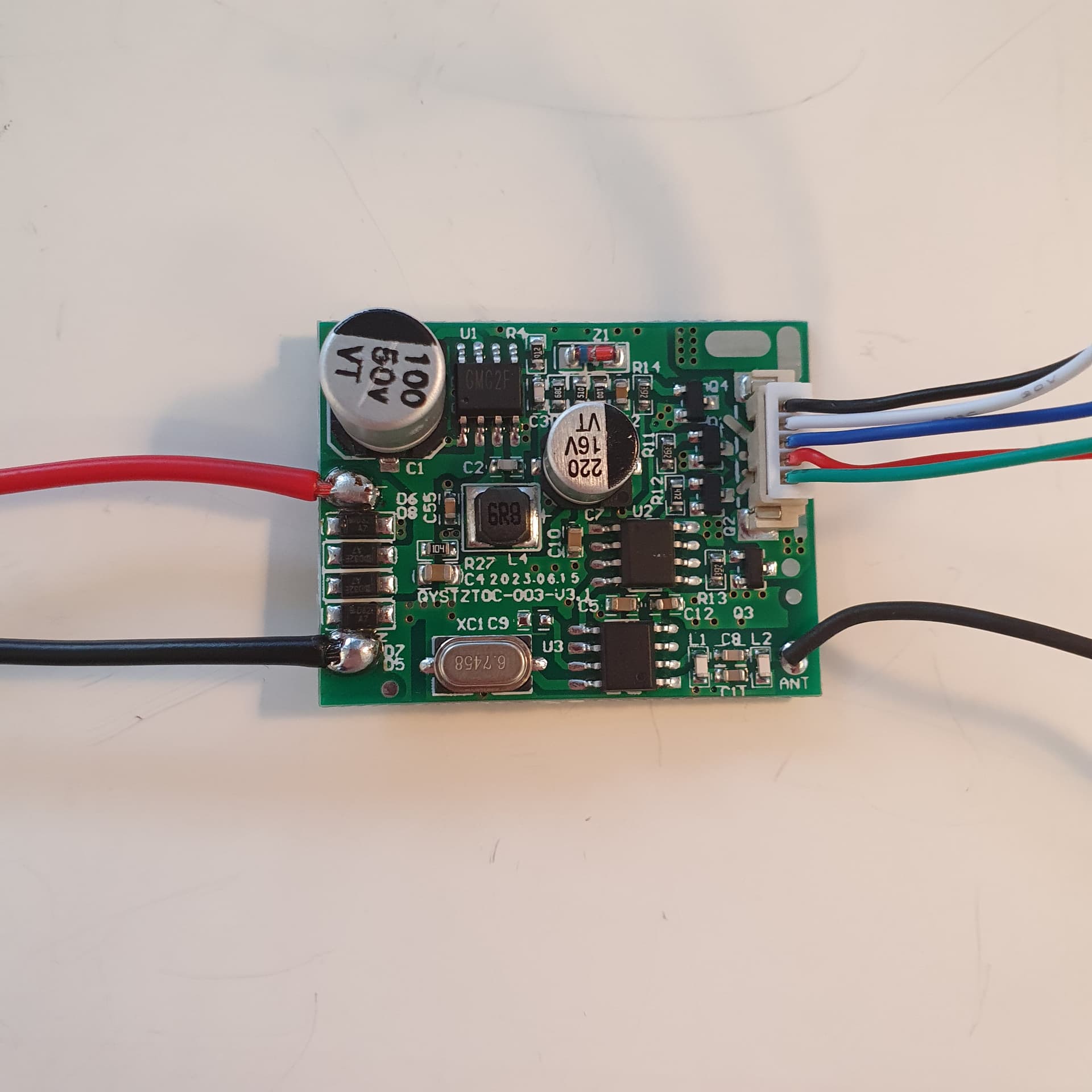

After a bit more research, this is what I have found:
12 - 24 V AC/DC in
Bridge rectifier
Top left chip (GMG 2F): Voltage regulator. Outputs 6,25 V DC on pin 3 (pin 4 =Ground)
Top right chip: 5V logic PWM outputs to Mosfets in full color mode:
White LED: 4,98 V / Red LED: 4,21 V / Green LED: 4,67 V / Blue LED: 4,67 V
Y1 N-Channel Mosfets: Between the PWM chip and the Gate pin of the Mosfets. there is a resistor. For White, Green and Blue : 3,9K For Red: 4,7 K
LED's on the other PCB: 6 X 5054 2W RGBW LEDs in parallel.
Forward Voltage: Red: 2,0-2,4 / Green: 2,8-3,2 / Blue: 3,0-3,4 / White: 2,8-3,4
Makes sense that the output voltage to the Red LED is lower, and that its has a larger resistor because of the lower Forward Voltage, quite common with Red LEDs.
LED strips I have used usually has resistors in the strip, next to the LEDs. Like a 150 ohm for Green and Blue and a 330 ohm for Red.
I don't understand the values though. The strips use 12V and has 150 - 330 ohm resistors, and these Spotlights use 6V and 3,9 -4,7 K ???
Must be some basic electronics I don't understand here.
Please explain if you want ![]()
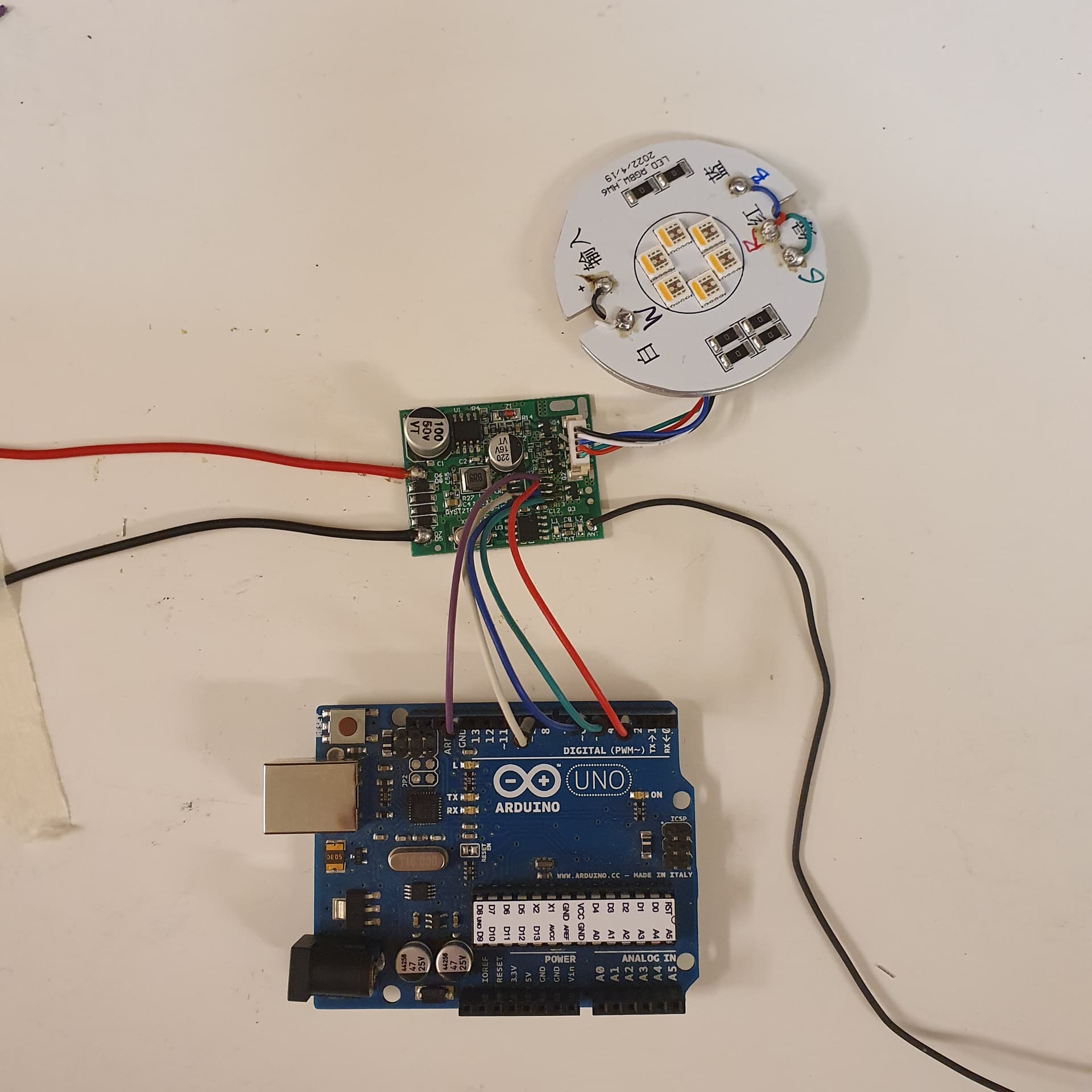
I will try the same setup with an Arduino PWM pins, and IRLB 8721 N-channel Mosfets.
If I use the same voltage and resistor values, I should get about the same effect.
Are they normally dimmable? I'd guess not with an input voltage spec of 12-24V. As the voltage varies it tries to hold the correct brightness.
The "PWM" is probably in the feedback loop of a switch-mode constant-current supply. That's how most high-power LEDs work... Either with a constant-current or variable controlled-current source, which means there isn't a power-wasting resistor in series to limit/control the current.
Here is an example of a dimmable LED driver. You need to know the current requirements of the LEDs and find a driver to match.
With a constant-current source you just need to feed-in sufficient voltage and when the current is right the voltage "falls into place". Basically the opposite of how everything else in electronics works...
I don't know if they are dimmable, but like you say, probably not.
Does that apply to the LEDs them selves, or the controlling circuit?
The remote has light level up and down buttons.
Do you think I can control them like I suggest with PWM and Mosfets?
Thanks for the suggestion.
I have looked more into it, and it seems like RGB LED strips is quite different to these Spotlights.
I thought I could control these with the same circuit I use for the strips, just 12V, Mosfet and PWM.
Looks like you know a lot about this reading some of your other posts.
You are probably right about the circuit in the driver being a switch mode constant current supply.
I don't know what all the parts do in the circuit, but I am guessing the bottom chip with the x-tal is the micro controller, taking input from the remote control, and relling the chip above to control the RGBW channels according to the program: strobe / blend / color by with a specific voltage on each pin, I am guessing with PWM.
I am now hoping I can desolder that chip, and connect the 4 output pins for each color to PWM pins on the Arduino ![]()
It's worth a try anyway
The 6.7458 MHz crystal is for a reference clock for some 433.92 MHz [ISM band] transmitters and receivers so the chip it is wired to is probably the receiver for the remote. There may be another chip that is the microcontroller rather than the chip associated with the crystal if that has any affect on finding which chip to remove.
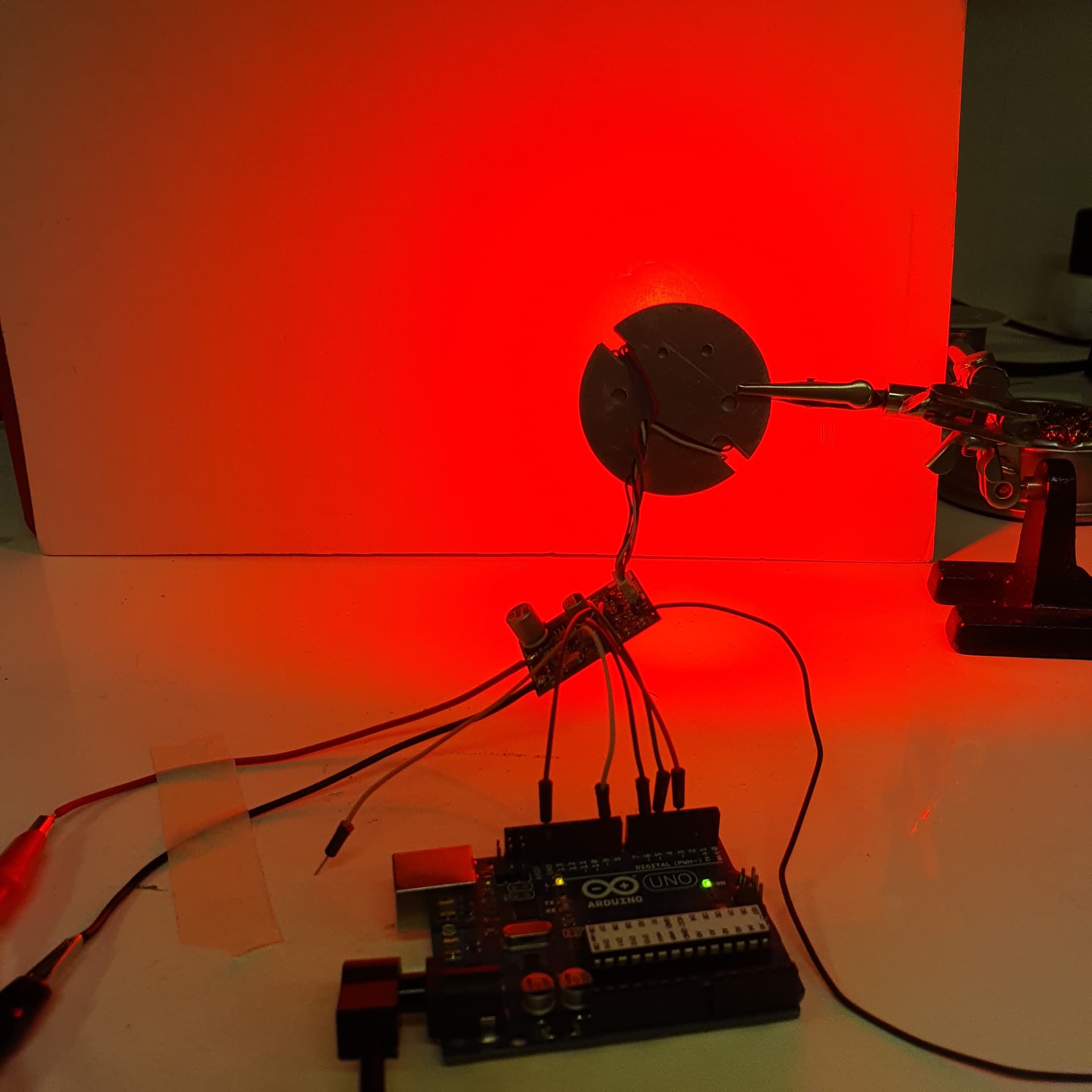
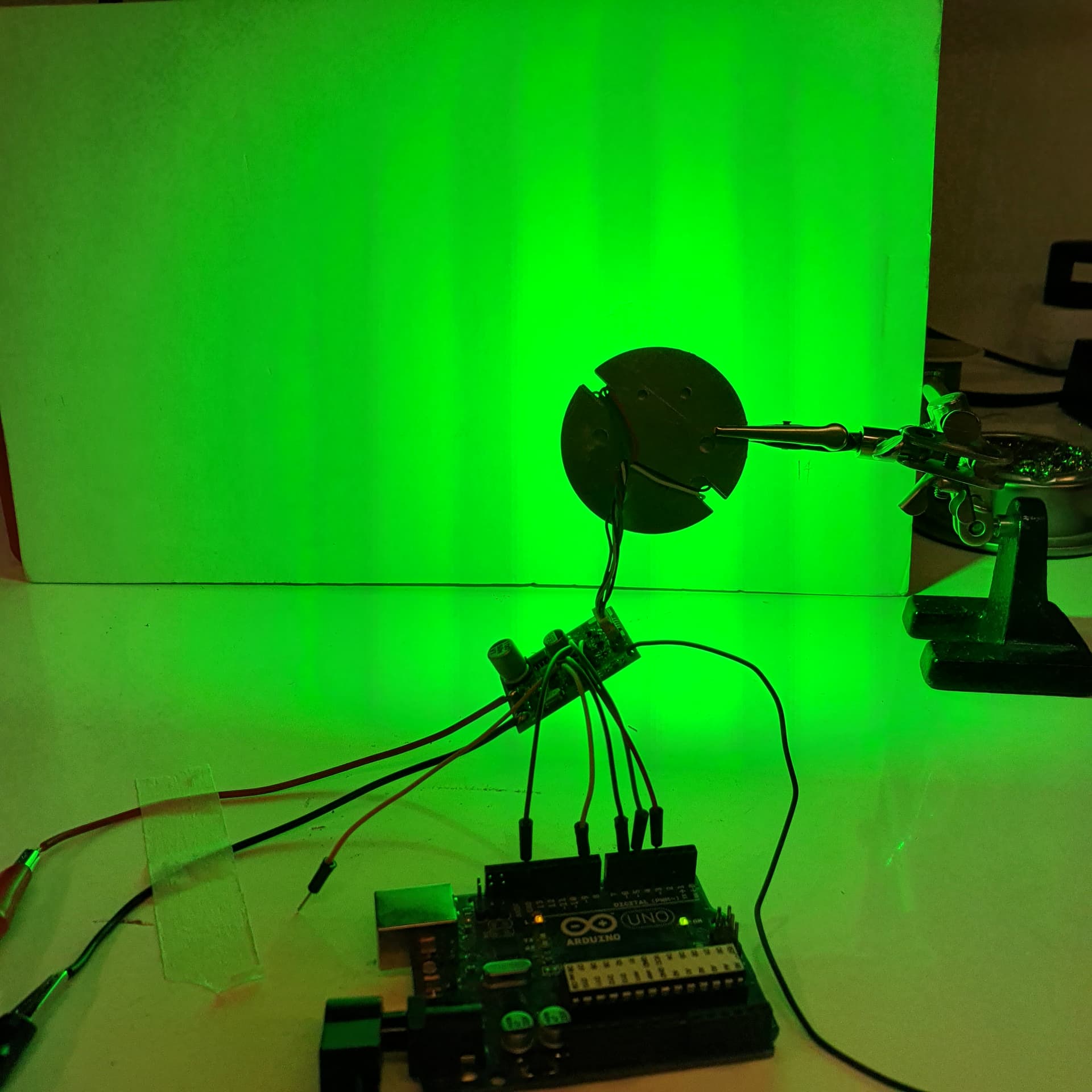
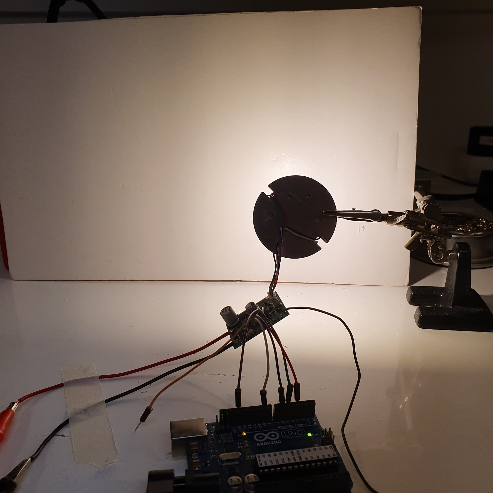
That worked great.
Removed the U2-chip, and soldered wires to the 4 pads that goes to the Gate pin on the Mosfets through a resistor, and a wire to Ground. Connected them to 4 PWM pins on the Arduino, and now I can control / dim them with PWM.
To stick with the voltages I read on the U2-chip when each color is on max, the Red has max 215, Blue and Green 240 and White 254

This topic was automatically closed 180 days after the last reply. New replies are no longer allowed.