Please be clear about what you are asking. Are you asking someone to change the code so that it acts as you need for your project? Or are you asking if it is possible or impossible to do?
// rotary encoder demo by 'jurs' for Arduino Forum
// This is the code for the main "sketch"

#include "encoder.h"
#define BAUDRATE 115200L // serial baud rate

void setup() {
  Serial.begin(BAUDRATE);
  Serial.println();
  Serial.println("Good night and good luck!"); // print some Test-Message at beginning
  beginEncoders();
}

void printEncoders()
{ // print current count of each encoder to Serial
  for (int i=0; i<NUMENCODERS; i++)
  {
    Serial.print(encoder[i].count);
    Serial.print('\t');
  }
  Serial.println();
}

void loop() {
  if (updateEncoders()) printEncoders();
}
and encoder.h
// rotary encoder include file by 'jurs' for Arduino Forum
// This is the code for a new "Tab" within the sketch with Tab name "encoder.h"
#include <Arduino.h>
struct rotary_t {byte pinA; byte pinB; int count;};

rotary_t encoder[]={
 {A4,A5},
};

#define NUMENCODERS (sizeof(encoder)/sizeof(encoder[0]))

volatile byte state_ISR[NUMENCODERS];
volatile int8_t count_ISR[NUMENCODERS];

void startTimer2()  // start TIMER2 interrupts
{
  noInterrupts();
  // Timer 2 CTC mode
  TCCR2B = (1<<WGM22) | (1<<CS22)  | (1<<CS20);
  TCCR2A = (1<<WGM21);
  OCR2A = 124;   // 249==500,  124==1000 interrupts per second
                 // 63 ==2000,  31==4000
                 // 15 ==8000,   7==16000
  TIMSK2 = (1<<OCIE2A); // enable Timer 2 interrupts
  interrupts();
}

void stopTimer2() // stop TIMER2 interrupts
{
  noInterrupts();
  TIMSK2 = 0;
  interrupts();
}

int8_t readEncoder(byte i)
{ // this function is called within timer interrupt to read one encoder!
  int8_t result=0;
  byte state=state_ISR[i];
  state= state<<2 | (byte)digitalRead(encoder[i].pinA)<<1 | (byte)digitalRead(encoder[i].pinB);
  state= state & 0xF;   // keep only the lower 4 bits
  /* // next two lines would be code to read 'quarter steps'
  if (state==0b0001 || state==0b0111 || state==0b1110 || state==0b1000) result= -1;
  else if (state==0b0010 || state==0b1011 || state==0b1101 || state==0b0100) result= 1;
  */
  // next two lines is code to read 'full steps'
  if (state==0b0001) result= -1;
  else if (state==0b0010) result= 1;
  state_ISR[i]= state;
  return result;
}

void beginEncoders()
{ // active internal pullup resistors on each encoder pin and start timer2
  for (int i=0; i<NUMENCODERS; i++)
  {
    pinMode(encoder[i].pinA, INPUT_PULLUP);
    pinMode(encoder[i].pinB, INPUT_PULLUP);
    readEncoder(i); // Initialize start condition
  }
  startTimer2();
}

boolean updateEncoders()
{ // read all the 'volatile' ISR variables and copy them into normal variables
  boolean changeState=false;
  for (int i=0; i<NUMENCODERS; i++)
  {
    if (count_ISR[i]!=0)
    {
      changeState=true;
      noInterrupts();
      encoder[i].count+= count_ISR[i];
      count_ISR[i]=0;
      interrupts();
    }
  }
  return changeState;
}


ISR(TIMER2_COMPA_vect)  // handling of TIMER2 interrupts
{
  for (int i=0; i<NUMENCODERS; i++)
  {
    count_ISR[i]+= readEncoder(i);
  }
}
/* SevSeg Counter Example
Copyright 2017 Dean Reading
Licensed under the Apache License, Version 2.0 (the "License");
you may not use this file except in compliance with the License.
You may obtain a copy of the License at
http://www.apache.org/licenses/LICENSE-2.0
Unless required by applicable law or agreed to in writing, software
distributed under the License is distributed on an "AS IS" BASIS,
WITHOUT WARRANTIES OR CONDITIONS OF ANY KIND, either express or implied.
See the License for the specific language governing permissions and
limitations under the License.
This example demonstrates a very simple use of the SevSeg library with a 4
digit display. It displays a counter that counts up, showing deci-seconds.
*/
#include "SevSeg.h"
SevSeg sevseg; //Instantiate a seven segment controller object
void setup() {
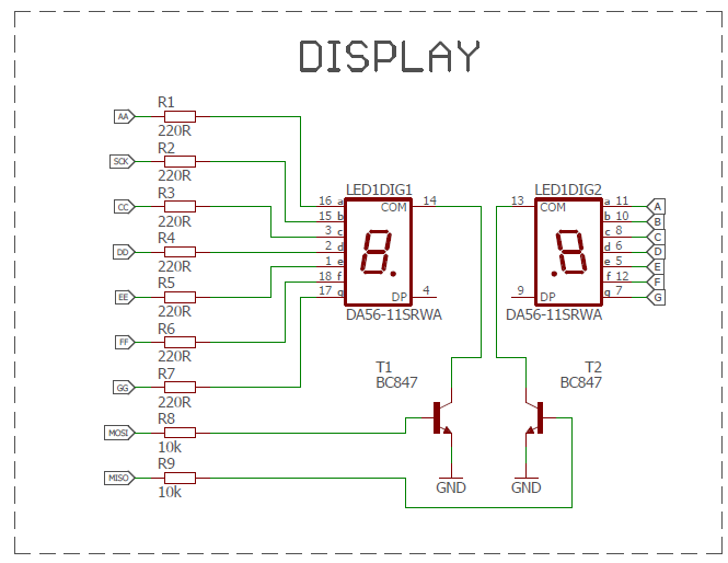
byte numDigits = 2;
byte digitPins[] = {12,11};
byte segmentPins[] = {10, 13, A2, A1, A0, 9, A3};
bool resistorsOnSegments = true; // 'false' means resistors are on digit pins
byte hardwareConfig = N_TRANSISTORS; // See README.md for options
bool updateWithDelays = false; // Default. Recommended
bool leadingZeros = false; // Use 'true' if you'd like to keep the leading zeros
sevseg.begin(hardwareConfig, numDigits, digitPins, segmentPins, resistorsOnSegments, updateWithDelays, leadingZeros);
sevseg.setBrightness(90);
}
void loop() {
static unsigned long timer = millis();
static int deciSeconds = 0;
if (millis() - timer >= 100) {
timer += 100;
deciSeconds++; // 100 milliSeconds is equal to 1 deciSecond
if (deciSeconds == 10000) { // Reset to 0 after counting for 1000 seconds.
deciSeconds=0;
}
sevseg.setNumber(deciSeconds, 1);
}
sevseg.refreshDisplay(); // Must run repeatedly
}
/// END ///
but now I dont know how to:
set limit for encoder to read values in range 0...64
How many relays do you want to use, and what type? Are they relay modules or bare relays?
You may run out of pins. One way to avoid that would be to use shift registers to drive the relays and the display. For the displays, use 2 x 74hc595. For the relay modules, use more 74hc595. For bare relays, use tpic6c595. All the shift registers can be daisy chained so only 3 ago pins are needed.
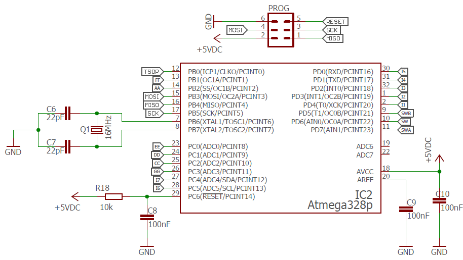
6 relays. All drive by ULN2003 (I1,I2,I3,I4,I5,I6,I7 (I7 additionall relay))
I know about shift registers, I have used them with last projects with 16ch led backlight for potentiometer but now I would like to use standard pins from atmega328p.
// rotary encoder demo by 'jurs' for Arduino Forum
// This is the code for the main "sketch"

#include "encoder.h"
#define BAUDRATE 115200L // serial baud rate

void setup() {
  Serial.begin(BAUDRATE);
  Serial.println();
  Serial.println("Good night and good luck!"); // print some Test-Message at beginning
  beginEncoders();
}

void printEncoders()
{ // print current count of each encoder to Serial
  for (int i=0; i<NUMENCODERS; i++)
  {
    Serial.print(encoder[i].count);
    Serial.print('\t');
  }
  Serial.println();
}

void loop() {
  if (updateEncoders()) printEncoders();


}
encoder.h
// rotary encoder include file by 'jurs' for Arduino Forum
// This is the code for a new "Tab" within the sketch with Tab name "encoder.h"
#include <Arduino.h>
struct rotary_t {byte pinA; byte pinB; int count;};

rotary_t encoder[]={
 {A4,A5},
};

#define NUMENCODERS (sizeof(encoder)/sizeof(encoder[0]))

volatile byte state_ISR[NUMENCODERS];
volatile int8_t count_ISR[NUMENCODERS];

void startTimer2()  // start TIMER2 interrupts
{
  noInterrupts();
  // Timer 2 CTC mode
  TCCR2B = (1<<WGM22) | (1<<CS22)  | (1<<CS20);
  TCCR2A = (1<<WGM21);
  OCR2A = 124;   // 249==500,  124==1000 interrupts per second
                 // 63 ==2000,  31==4000
                 // 15 ==8000,   7==16000
  TIMSK2 = (1<<OCIE2A); // enable Timer 2 interrupts
  interrupts();
}

void stopTimer2() // stop TIMER2 interrupts
{
  noInterrupts();
  TIMSK2 = 0;
  interrupts();
}

int8_t readEncoder(byte i)
{ // this function is called within timer interrupt to read one encoder!
  int8_t result=0;
  byte state=state_ISR[i];
  state= state<<2 | (byte)digitalRead(encoder[i].pinA)<<1 | (byte)digitalRead(encoder[i].pinB);
  state= state & 0xF;   // keep only the lower 4 bits
  /* // next two lines would be code to read 'quarter steps'
  if (state==0b0001 || state==0b0111 || state==0b1110 || state==0b1000) result= -1;
  else if (state==0b0010 || state==0b1011 || state==0b1101 || state==0b0100) result= 1;
  */
  // next two lines is code to read 'full steps'
  if (state==0b0001) result= -1;
  else if (state==0b0010) result= 1;
  state_ISR[i]= state;
  return result;
}

void beginEncoders()
{ // active internal pullup resistors on each encoder pin and start timer2
  for (int i=0; i<NUMENCODERS; i=63)
  {
    pinMode(encoder[i].pinA, INPUT_PULLUP);
    pinMode(encoder[i].pinB, INPUT_PULLUP);
    readEncoder(i); // Initialize start condition
  }
  startTimer2();
}

boolean updateEncoders()
{ // read all the 'volatile' ISR variables and copy them into normal variables
  boolean changeState=false;
  for (int i=0; i<NUMENCODERS; i++)
  {
    if (count_ISR[i]!=0)
    {
      changeState=true;
      noInterrupts();
      encoder[i].count = constrain(encoder[i].count + count_ISR[i], 0, 63);
      count_ISR[i]=0;
      interrupts();


    }
  }
  return changeState;
}


ISR(TIMER2_COMPA_vect)  // handling of TIMER2 interrupts
{
  for (int i=0; i<NUMENCODERS; i++)
  {
    count_ISR[i]+= readEncoder(i);
  }
}
Now I think it will be easier (maybe not for me... ). To get actual value I need to write:
encoder[i].count
Right?
( encoder*.count ==> after updateEncoders(); this int will contain the current count value )* In void loop: * *if (encoder[i].count = 1) { digitalWrite(Relay1, HIGH) }* *
Perhaps. We still do not understand the purpose of your project. If you have only 6 or 7 relays, what will encoder values 8 to 63 do? How will the relays be switched off?