Hi all,
started from scratch almost (Basic stamp about 10+yrs ago minimal use) 2 days ago using the Uno board and writing code!!
After using a book for reference (Programming Arduino by Simon Monk) and the good old web for info and researching, im pretty happy with my build and coding so far.
But...
I've hit a brick wall and im looking for a fresh direction on code to try to solve the issue. ![]()
Question: How can i translate a numeric reading generated from my 'Rotary incremental Optical Encoder' to show rotational degrees (0-359 per revolution) in my sketch so that i can handle that better in my code?
As you can see in my sketch i get a signal count of 720 pulses per 360 degrees of the encoder (360ppr encoder, A+B inputs = 720).
I have set a reset for count = '0' if >719 so the count doesn't max out at 65535 and then back to 0 again which clearly is no use to me for the application. This gives me currently a 720ppr to handle in the code for my timings. '0' counted as a position so 719 max is 720 in real terms per revolution.
Although it works great at the moment it has a few failings in the use of the count and not actual degrees.
Issue:
If you rotate in reverse the outputs work fine as the count decreases but the value goes '0' and will not cycle to 719 and reduce again as it is a pulse count. This then affects '0' position (or TDC if you prefer) and has the affect of putting all timings out of the fixed datum position on the machine being TDC at a given fixed point in the machines cycle.
Result: All timings, all correct relative to each other but all out on the machine.
Solution: Translate count to rotational degrees, 0-359 to 0 again in one full forward revolution. Reverse encoder rotation shows 359-0 and 359 again. Modify required timings for outputs in 0-359 range in code.
###Sketch as follows### (first post so probably attached sketch incorrectly..sorry)
/*Electronic Cam switch sketch V.Sep25.1
* Industrial application
*
* Requirement to control various low voltage solenoids 'off/on/off' and sensor 'sense' timings repeatedly per 360 degree revolution
* from a mechanical shaft rotating once per machine cycle.
* Proximity sensor will enable absolute TDC at '0' degrees on machine for reliable timing per revolution. Acting as a Reset.
* Sensor maybe be uninstalled if code makes obsolete and retains Encoder absolute position after power down/up. Encoder mounted on fixed position on machine shaft.
Equipment required:
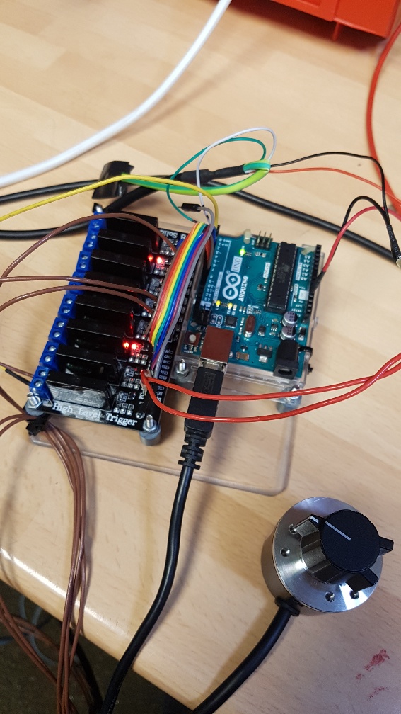
Arduino Uno
8x solid state relay shield, 5vdc control voltage
Encoder type: LPD3806-360BM-G5-24C 360PPR (translates to 720ppr on count due to signal inputs A+B)
Connections: Red 5-24 vdc
Black 0v ground
Green Input A
White Input B
Cable braid Ground to isolate possible interference form machine
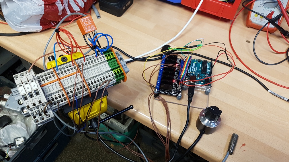
Proximity sensor: Baumer IFRM 12P1702/L. 5-24vdc range.
Arduino Input(5) wired through SSR no.1 using 5v load voltage to isolate non 5v proximity sensor output voltage. Not needed if 5v used.
- external relay used to switch 12-24vdc output of proximity sensor etc. This may change when additional 5vdc power supply installed on machine.
*/
volatile unsigned int counter = 0; //This variable will increase or decrease depending on the rotation of encoder
void setup() {
Serial.begin (9600);
pinMode(2, INPUT_PULLUP); // internal pullup input pin 2 for encoder input A - green wire
pinMode(3, INPUT_PULLUP); // internal pullup input pin 3 for encoder input B - white wire
pinMode(5, INPUT); // set pin to input - proximity sensor looped through SSR #1 to isolate 12vdc signal to 5vdc input on Micro PLC.
pinMode(6, OUTPUT); // set pin to output - SS relay #2 on relay board
pinMode(7, OUTPUT); // set pin to output - SS relay #3 on relay board
pinMode(8, OUTPUT); // set pin to output - SS relay #4 on relay board
pinMode(9, OUTPUT); // set pin to output - SS relay #5 on relay board
pinMode(10, OUTPUT); // set pin to output - SS relay #6 on relay board
pinMode(11, OUTPUT); // set pin to output - SS relay #7 on relay board
pinMode(12, OUTPUT); // set pin to output - SS relay #8 on relay board
//Setting up interrupt
//A rising pulse from encodenren activated ai0(). AttachInterrupt 0 is DigitalPin nr 2 on moust Arduino.
attachInterrupt(0, ai0, RISING);
//B rising pulse from encodenren activated ai1(). AttachInterrupt 1 is DigitalPin nr 3 on moust Arduino.
attachInterrupt(1, ai1, RISING);
}
void loop() {
// Send the value of counter (debug - remember to comment out before final program run,
// you don't want serial slowing down your program if not needed)
Serial.println (counter);
if (counter >719) {
counter = 0;
}
// if (digitalRead(5)==HIGH) { (TEMP BLOCKED OUT AS FOR SOME REASON NOT FUNCTIONING FULLY) WORK AROUND LATER ;), wiring logic correct, sketch not liking the code,
// counter = 0;
}
void ai0() {
// ai0 is activated if DigitalPin nr 2 is going from LOW to HIGH
// Check pin 3 to determine the direction
if(digitalRead(3)==LOW) {
counter++;
}else{
counter--;
}
}
void ai1() {
// ai0 is activated if DigitalPin nr 3 is going from LOW to HIGH
// Check with pin 2 to determine the direction
if(digitalRead(2)==LOW) {
counter--;
}else{
counter++;
}
if (counter <100) digitalWrite(6, LOW);{
}
if ((counter >=100) && (counter <=200)) digitalWrite(6, HIGH);{
}
if (counter >200) digitalWrite(6, LOW);{
}
if (counter <200) digitalWrite(7, LOW);{
}
if ((counter >=200) && (counter <=300)) digitalWrite(7, HIGH);{
}
if (counter >300) digitalWrite(7, LOW);{
}
if (counter <300) digitalWrite(8, LOW);{
}
if ((counter >=300) && (counter <=400)) digitalWrite(8, HIGH);{
}
if (counter >400) digitalWrite(8, LOW);{
}
if (counter <400) digitalWrite(9, LOW);{
}
if ((counter >=400) && (counter <=500)) digitalWrite(9, HIGH);{
}
if (counter >500) digitalWrite(9, LOW);{
}
if (counter <100) digitalWrite(10, LOW);{
}
if ((counter >=100) && (counter <=200)) digitalWrite(10, HIGH);{
}
if (counter >200) digitalWrite(10, LOW);{
}
if (counter <200) digitalWrite(11, LOW);{
}
if ((counter >=200) && (counter <=300)) digitalWrite(11, HIGH);{
}
if (counter >300) digitalWrite(11, LOW);{
}
if (counter <300) digitalWrite(12, LOW);{
}
if ((counter >=300) && (counter <=400)) digitalWrite(12, HIGH);{
}
if (counter >400) digitalWrite(12, LOW);{
}
}
Any help would be appreciated. I'm Using the Arduino for this application as im many years with industrial control systems electrically but not PLC and programming so thought this is an ideal chance to finally get more skilled in the world or Arduino. Impressed so far!
I've a few projects in my head for collecting telemetry from by motorbike on track days but first things first and learn the basics.
Thanks for looking at my lengthy post but info is king in my world.
Gav.
26/09/18
12:32 GMT
UK.