Hello Arduino Gurus!
I bought some cheap qurature rotary encoders on amazon manufactured by WGCD, with the model number KY-040 (all internet research I have done points to them being made by Keyes, but there is no marking on the PCB board at all so I assume these are cheap clones).
I got them to learn how to use rotary encoders and play with some cheap Nano clones from Elegoo.
I found this schematic for the encoder, and have attached the encoder's ground pin to the arduino's ground pin, the encoders + pin to the arduino's 5V pin, and the arduino is being powered by it's USB port connected to my laptop. A cheap multimeter reading from the arduino's 5V pin to ground reads 4.65V. The rotary encoder's CLK pin is attached to pin 3 and the DT pin is attached to pin 4 or 2, depending on the experiment.
I have run into two very weird situations when trying to read the encoders.
First: When attaching an interrupt to the "clock" pin, MANY interrupts fire at the edges of events. Sometimes as many as 26. I wrote some simple code to measure them:
const byte clkPin = 3;

volatile int clkIntCount;

#define MSG_LEN 35
char msg[MSG_LEN];

void setup() {
  pinMode(clkPin, INPUT);
  clkIntCount = 0;
  Serial.begin(115200);
  while (!Serial)
    delay(10);
  Serial.println("Attaching interrupt...");
  attachInterrupt(digitalPinToInterrupt(clkPin), clkPinInterrupt, CHANGE);
}

void loop() {
  int clkIntCount_l;
  noInterrupts();
  clkIntCount_l = clkIntCount;
  clkIntCount = 0;
  interrupts();
  if (clkIntCount_l > 0) {
    snprintf(msg, MSG_LEN, "Interrupt triggered %i times", clkIntCount_l);
    Serial.println(msg);
  }
}

void clkPinInterrupt() {
  clkIntCount++;
}
Shows this output, where each pair of two prints is one detent of turn on the encoder, a couple of seconds apart:
Attaching interrupt...
Interrupt triggered 5 times
Interrupt triggered 2 times
Interrupt triggered 12 times
Interrupt triggered 3 times
Interrupt triggered 3 times
Interrupt triggered 3 times
Thinking that maybe the pin is switching state a bunch of times from bounce, plotted the pin state along with the count of times interrupt is being fired (the led blink is to let me know when it will record so I can move the rotary encoder, and the pause is so i can screenshot the graph):
const byte clkPin = 3;

volatile int clkPinIntState;
volatile int clkIntCount;

void setup() {
  pinMode(clkPin, INPUT);
  pinMode(LED_BUILTIN, OUTPUT);
  clkPinIntState = digitalRead(clkPin);
  clkIntCount = 0;

  attachInterrupt(digitalPinToInterrupt(clkPin), clkPinInterrupt, CHANGE);

  Serial.begin(115200);
  while (!Serial)
    delay(10);
}

void loop() {
  int clkIntCount_l;
  digitalWrite(LED_BUILTIN, HIGH);
  delay(250);
  digitalWrite(LED_BUILTIN, LOW);
  delay(250);
  digitalWrite(LED_BUILTIN, HIGH);

  for (int i = 0; i < 3000; i++) {
    noInterrupts();
    clkIntCount_l = clkIntCount;
    clkIntCount = 0;
    interrupts();
    Serial.print(clkPinIntState == HIGH ? "-1.0" : "-2.0");
    Serial.print(" ");
    Serial.println(clkIntCount_l);
  }
  digitalWrite(LED_BUILTIN, LOW);
  delay(10000);
}

void clkPinInterrupt() {
  clkIntCount++;
  clkPinIntState = digitalRead(clkPin);
}

Is this normal? Is there a way to reduce the interrupt sensitivity? From the pin readings, it looks like the value is not bouncing, and the threshold from high to low only happens once when the interrupt is triggered 10+ times. I suppose one approach would be to record each time an interrupt happened, and then check after some amount of time that no more have been triggered...
Second: This one is a real head scratcher. I couldn't understand why my interrupt based rotary encoder code was reading very strange result (bouncing back and forth), so I wrote a simple plotter program and plugged both clk and dt into analog pins, then plotted their outputs. Very clean square waves that look exactly as expected. So I put them back onto the digital pins, and did the same, and got the same result. very clean state transitions with no bouncing in state. So then I wrote another plotter to log the value of the clk and dt pin in the loop, as well as separately in the interrupt for clk. This is where things got weird.
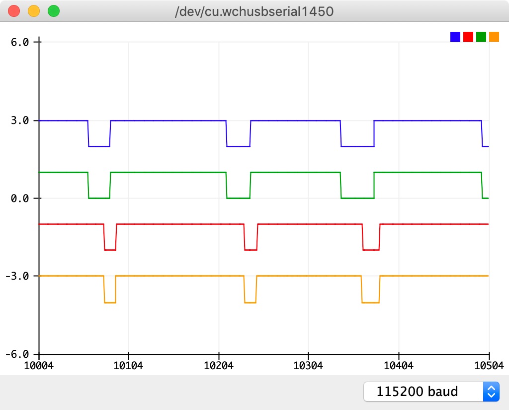
When I have the clk pin configured as an interrupt, and the dt pin on any other digital pin (I tried a few... all produced the same results), if I read both pin's states in the interrupt, the dt pin is the inverse of the clk pin. always. but when both pins are read in the loop, they are as expected. what?! So I setup interrupts for both pins, and then they read correctly. Am I to believe that I can't read any of the digital input pins other than the interrupt triggering pin in the interrupt routine? I didn't see that anywhere in the documentation. Here is some code and graphs to show what I saw:
Read pin values in the clk interrupt and in the loop:
const byte clkPin = 3;
const byte dtPin = 2;

int clkPinState;
int dtPinState;

volatile int clkPinIntState;
volatile int dtPinIntState;

void setup() {
  pinMode(clkPin, INPUT);
  pinMode(dtPin, INPUT);
  pinMode(LED_BUILTIN, OUTPUT);
  clkPinIntState = clkPinState = digitalRead(clkPin);
  dtPinIntState = dtPinState = digitalRead(dtPin);

  attachInterrupt(digitalPinToInterrupt(clkPin), clkPinInterrupt, CHANGE);

  Serial.begin(115200);
  while (!Serial)
    delay(10);
}

void loop() {
  digitalWrite(LED_BUILTIN, HIGH);
  delay(500);
  for (int i = 0; i < 700; i++) {
    clkPinState = digitalRead(clkPin);
    dtPinState = digitalRead(dtPin);

    Serial.print(clkPinState == HIGH ? "3.0" : "2.0");
    Serial.print(" ");
    Serial.print(dtPinState == HIGH ? "-1.0" : "-2.0");
    Serial.print(" ");
    Serial.print(clkPinIntState == HIGH ? "1.0" : "0");
    Serial.print(" ");
    Serial.println(dtPinIntState == HIGH ? "-3.0" : "-4.0");
  }
  digitalWrite(LED_BUILTIN, LOW);
  delay(10000);
}

void clkPinInterrupt() {
  clkPinIntState = digitalRead(clkPin);
  dtPinIntState = digitalRead(dtPin);
}

After updating the code so that clk and dt each have their own interrupts, the pin values read during the interrupt make sense:
const byte clkPin = 3;
const byte dtPin = 2;

int clkPinState;
int dtPinState;

volatile int clkPinIntState;
volatile int dtPinIntState;

void setup() {
  pinMode(clkPin, INPUT);
  pinMode(dtPin, INPUT);
  pinMode(LED_BUILTIN, OUTPUT);
  clkPinIntState = clkPinState = digitalRead(clkPin);
  dtPinIntState = dtPinState = digitalRead(dtPin);

  attachInterrupt(digitalPinToInterrupt(clkPin), clkPinInterrupt, CHANGE);
  attachInterrupt(digitalPinToInterrupt(dtPin), dtPinInterrupt, CHANGE);

  Serial.begin(115200);
  while (!Serial)
    delay(10);
}

void loop() {
  digitalWrite(LED_BUILTIN, HIGH);
  delay(500);
  for (int i = 0; i < 700; i++) {
    clkPinState = digitalRead(clkPin);
    dtPinState = digitalRead(dtPin);

    Serial.print(clkPinState == HIGH ? "3.0" : "2.0");
    Serial.print(" ");
    Serial.print(dtPinState == HIGH ? "-1.0" : "-2.0");
    Serial.print(" ");
    Serial.print(clkPinIntState == HIGH ? "1.0" : "0");
    Serial.print(" ");
    Serial.println(dtPinIntState == HIGH ? "-3.0" : "-4.0");
  }
  digitalWrite(LED_BUILTIN, LOW);
  delay(10000);
}

void clkPinInterrupt() {
  clkPinIntState = digitalRead(clkPin);
}

void dtPinInterrupt() {
  dtPinIntState = digitalRead(dtPin);
}
Epilogue
Ideally, I'd like to have an interrupt on the CLK pin, record the values of both CLK and DR, and set a flag, and then in the program loop when that flag is set, decode the direction that the rotary encoder moved. But since I'm getting tons of extra interrupts and I can't read the DT pin in the interrupt, I'm a little stuck. I can think of some workarounds for the latter (like waiting to check DT until the loop), but the former is a bit disconcerting.
I have read quite a few articles on debouncing switches and rotary encoders, and a lot of them implement filters on the state transitions, which make sense, but the state transitions don't appear to be bouncing around, and the pin value being read incorrectly is really weird.
I ordered a pack of resistors and capacitors, and i'll try putting a capacitor on the CLK and DT pins to ground to see if that reduces the number of interrupt triggers.
Any advice would be appreciated!
-Dan