Rotating Dispensor

I am new to the community but I have some experience from college and individual creations.

I am having difficulty getting a wagon wheel type mechanism to rotate 360 degrees accurately every time. However after I have entered my code into the "NodeMCU1.0" it doesn't accurately turn 360 degrees over any given time period - it varies per rotation. I understand that the steps/pulses per revolution have to be factored in, but that was not provided from the manufacturer.

I am intending to use worm gear motor to spin the wheel which is partitioned every 22.5 degrees. Creating a 24 hour pause between 22.5 degree spins. Or 1/16th of 360%.

The code I am using below is what I am using to determine the steps per rotation by changing the "analogeWrite" and "delay times".

Item List:

  • (Greartisan) DC 12V 45RPM Worm Geared Motor High Torque Turbine Worm Gear Box Reduction Motor 6mm Shaft JSX180-370
  • L298N DC Motor Drive Controller Board
  • Node MCU Esp 8266

CODE BELOW

int ENA = 4;
int IN1 = 0;
int IN2 = 2;

void setup() {

// set all the motor control pins to outputs

pinMode(ENA, OUTPUT);
pinMode(IN1, OUTPUT);
pinMode(IN2, OUTPUT);
}
// turn on motor
digitalWrite(ENA, HIGH); 
digitalWrite(IN1, HIGH);
digitalWrite(IN2, LOW);

analogWrite(ENA, 200);// set speed to 200 out of possible range 0~255

delay(60000); //0.1 sec per 100 or .5 sec per 500ms:  2000 = 2 secs 
                         //now turn off motors 1 day = 86400000 and 750 ms to make one rotation//

digitalWrite(IN1, LOW);
digitalWrite(IN2, LOW);
}
void loop() {  
                                 //Delay 1 SEC Loop
	delay(1000);   
  	
}

Screenshot 2024-03-23 124750

My problem using the code above, the motor rotates more than 360 degrees making its home point off every time. Ive been searching the internet for calculations to work out the (Steps/Pulses) of the motor. For example if it rotates 45 RPM, after 45 rotations it stops ahead of its start point at about +15 Degrees but that number varies every time the code is executed by loop.

Any help would be extremely appreciated. This is my first post so please correct my ignorance if I have failed to interpret to the forum guidelines.

Im a disabled vet that takes pills once a day and I am trying to create a dispenser that drops them into a shute every 24hours. (Pill Cases are not helpful for me since their size is too large) My 3D print makes a 4 month pill dispenser into a 3 inch by 4 inch mechanism.

If my hardware is wrong, please advise so. If my code is causing the inaccuracy please point that out.

Thank you so much for your time and expertise !

Oh by the way, this isn't a school project, its more of a personal use item out of necessity. Memory is bad when it comes to day to day things.

John

RPM stands for revolutions Per Minute. It has nothing to do with steps per rev.

A DC motor has no steps per rev. Its RPM is not precise at all, varies from unit to unit and to the load.

Consider a stepper and stepper driver. The L298N is not capable of running current controlled steppers.

1 Like

Great Thank you so much for your guidance. I thought I was off onto a wild goose chase.

Thanks. Using a stepper You need to have a good idea about the torque needed. Then the stepper can be selected and then the driver.
Continues rotating servo motor is thinkable but calls for RPM measuring and PID control.

1 Like

my torque will be incredibly minimal. A basic Arduino 5v stepper motor had it turning but it was just outside its torque capabilities. I chose the DRV8825 driver module with the Nema 17 Stepper motor. It has a lower profile and would decrease my overall project size by half.

That sounds good but know that turning a wheel the radius multiplies the peripheral force giving torque.

Sounds like You need to test this rigging and report.

Please don't use the Arduino 5 volt for power. Use an external power supply.

1 Like

But, if the wheel were driven from the periphery it'd take a lot less torque to move it. Stepper turns the small gear, compartment wheel is the large gear. It would take more steps but, who cares?

1 Like

OK thanks for the advice. I have an external power source ready to go.

Oh man - lmao - I had to look up "Periphery" - good word. Hmmm I think that design change should be fairly easy. It would probably best if I added a bearing to the hub then have the "Periphery" with gear teeth. It would take the motor out of center but the gear on the axis of the stepper shaft could be made to keep it concealed.

For the OP!

It certainly does. Only it gears the RPM down but for low dispenser RPM it will likely not be a problem.

1 Like

Gotcha !! Will update you all on final project, thanks again =)

well for the past 5 days I have been working on this for hours. Here are my new parts.

DRV 8825 on Stepper Motor Expansion board.
ESP 8266 MOD D1MINI
Nema 17 Stepper Motor

And this code

const int dirPin = 0;
const int stepPin = 2;
const int stepsPerRevolution = 200;
 
void setup()
{
  // Declare pins as Outputs
  pinMode(stepPin, OUTPUT);
  pinMode(dirPin, OUTPUT);
}
void loop()
{
  // Set motor direction clockwise
  digitalWrite(dirPin, HIGH);
 
  // Spin motor slowly
  for(int x = 0; x < stepsPerRevolution; x++)
  {
    digitalWrite(stepPin, HIGH);
    delayMicroseconds(2000);
    digitalWrite(stepPin, LOW);
    delayMicroseconds(2000);
  }
  delay(1000); // Wait a second
  
  // Set motor direction counterclockwise
  digitalWrite(dirPin, LOW);
 
  // Spin motor quickly
  for(int x = 0; x < stepsPerRevolution; x++)
  {
    digitalWrite(stepPin, HIGH);
    delayMicroseconds(1000);
    digitalWrite(stepPin, LOW);
    delayMicroseconds(1000);
  }
  delay(1000); // Wait a second
}

board
D1MINI

Ive tried to show you my set up on a circuit but I couldnt find one that had all the components I am using.

My power is 12v 2amp Plug.
The plug is powering both the ESP8266 and Driver board. Both voltages and on each component are reading appropriate levels. (12v at driver board and 4.9 volts at the ESP 8266 MOD.

I replaced the pictured NodeMCU with the ESP 8266MOD smaller more compact type of controller board.

Im definately learning though.

The motor is not turning and however the DRV8825 and ESP8266 MOD are getting enough power.
Ive tried both steppers that I have - and both test good as operational.

Please forgive my ignorance here but I think its gotta be something very simple that I am missing.

IF there is anything else specific that I can provide you, please let me know.

Side note - when testing the Voltage on my DRV 8825 I get 0.0 voltage readings on my VIN/GND pins.

I have 4 DRV 8825s and they all test 0.0 volts at VIN/GND pins as the potentiometer of the DRV 8825 cannot be adjusted if there is no voltage readings. The Reading should be 0.17volts.

Ok you guys might want to ignore the code. Too many mistakes, Ill come back and address it later. I owe you at least a working code, too broken. - Stand By -

This is the updated code to reflect the D1MINI

Recheck your circuit. Then, draw a schematic by hand. This way you can label each component as it is in front of you. Include each and every connection in the circuit in front of you. Label each component pin by number and designation. Label power supply voltages where applicable.

Make it legible, with good contrast, and take a well-lit photo and post that to the thread.

2 Likes

Doug - Are you a mind reader? That is the most amazing piece of advice as I just finished doing just that and found the cause to my troubles. I jumped on here to read if anyone posted an update and there you were.

Sooo in short. Once I had drew my schematic and started checking each component, everything checked ok. Then I decided to check the load coming off of my power source - and it happened - Everything shut off (as far as power readings) It seems the most likely culprate was not investigated by me at the start properly.

When I tested the wiring of my power source, I discovered the wire was faultly and randomly opening when moved. I would move my project everytime to a location to test it in and thats when the wire would come loose. Once I replaced it and powered it up - everything worked exactly as it should.

In the end I owe you all a great deal of thanks. I will post the final product on here when its assembled. I think you all will find it pretty interesting. I will also put the schematics and code with photos so it may be reproduced properly.

Thanks again

John

Great!

:+1:

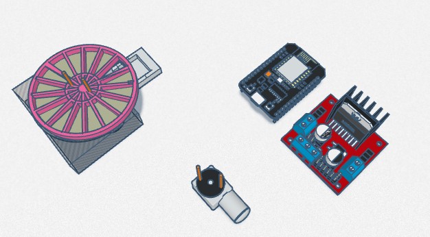
Here is my update for the project as promised. I ve decided to go with the DRV8825 Motor Driver, Nema 17 Stepper Motor, 7805 voltage regulator, DS3231 Clock module, 10 uF Cap on Volt Reg., 100uF Cap on Power 12V 2 Amps., red colored led, 10k resistor on button, and for the processing module I am using a NodeMCU 32S Dev Board. Attached is the schematics and code.

  • 1st problem - Led fails to light when triggered at time period designated in code.
  • 2nd problem - Nema 17 hums until called on and gets very hot.

Please see the code and the schematics for reference.

Thank you

John

#include <Arduino.h>
#include <LiquidCrystal_I2C.h>      // For LCD
#include <RTClib.h>                 // For RTC DS3231
#include <DRV8825.h>                // For Stepper Driver

#define setStepsPerRevolution 100

LiquidCrystal_I2C lcd(0x27,16,2);   // Create LCD with I2C address 0x27, 16 characters per line, 2 lines
RTC_DS3231 rtc;                     // Create RTC for the DS3231 RTC module

//time settings for pill dispensing at 6am

int Hr = 6;
int Min = 0;
int Sec = 0;


const int dirPin = 18;              // Pins 16, 17, 18 and 19 perminetly set to (ledPin, button, dirPin and stepPin)
const int stepPin = 19;
const int button = 17;
const int ledPin = 16;

//int buttonStateTwo = 0;             // Sets buttonTwo off at initial state
int buttonState = 0;                // Sets button off at initial state

// Minimum and maximum values structure for each input.
typedef struct minMax_t {
  int minimum;
  int maximum;
};
/*
   Function to validate user input.
   Returns TRUE if value in range, FALSE otherwise.
*/
bool checkInput(const int value, const minMax_t minMax) {
  if ((value >= minMax.minimum) &&
      (value <= minMax.maximum))
    return true;

  Serial.print(value);
  Serial.print(" is out of range ");
  Serial.print(minMax.minimum);
  Serial.print(" - ");
  Serial.println(minMax.maximum);
  return false;
}

/*
   Function to update RTC time using user input using "u" in serial input.
*////////////////////////////////////////////////////////////////////////////////////////////////////////
void updateRTC()
{

  lcd.clear();
  lcd.setCursor(0, 0);
  lcd.print("Edit Mode...");

  // Prompts for user input at "u" call. Sets paramaters for time.

const char txt[6][15] = { 
"year [4-digit]", "month [1~12]", "day [1~31]",
"hours [0~23]", "minutes [0~59]", "seconds [0~59]"
};
// Define limits of user inputs.
  const minMax_t minMax[] = {
    {2000, 9999},   // Year
    {1, 12},        // Month
    {1, 31},        // Day
    {0, 23},        // Hours
    {0, 59},        // Minutes
    {0, 59},        // Seconds
  };

  String str = "";

  long newDate[6];
  DateTime newDateTime;

  // The outer loop. Goes around and around until we get a valid
  // date and time. Thats all 6 inputs valid. It does not validate
  // February and/or leap years - it doesn't have to DateTime.isValid()
  // does that for us.

  while (1) {
    while (Serial.available()) {
      Serial.read();  // Clear serial buffer
    }

    // We have 6 different user inputs to capture.
    for (int i = 0; i < 6; i++) {

      // This loop exits when one user input is valid in
      // as far as being numeric and in range, sort of.
      // Leap years and month end dates are validated later
      // when we have the complete date and time.

      while (1) {
        Serial.print("Enter ");
        Serial.print(txt[i]);
        Serial.print(" (or -1 to abort) : ");

        while (!Serial.available()) {
          ; // Wait for user input
        }

        str = Serial.readString();  // Read user input
        // The actual value depends on the line ending configured in
        // the Serial Monitor. The configured line end character(s)
        // are part of the input string!
        // If the value is -1, then we abort the clock change
        // completely and bale out of this function.

        if ((str == "-1")   || (str == "-1\n") ||
            (str == "-1\r") || (str == "-1\r\n")) {
          Serial.println("\nABORTED");
          return;
        }

        newDate[i] = str.toInt();   // Convert user input to number and save to array

        // Validate input is in range, exit this inner while() loop
        // if so, otherwise, lets go round again.

        if (checkInput(newDate[i], minMax[i]))
          break;

      }

      Serial.println(newDate[i]); // Show user their input
    }
    
    newDateTime = DateTime(newDate[0], newDate[1], newDate[2], newDate[3], newDate[4], newDate[5]);
    if (newDateTime.isValid())
      break;

    
    Serial.println("Date/time entered was invalid, please try again.");
  }

  // Update RTC as we have a valid date & time.
  rtc.adjust(newDateTime);
  Serial.println("RTC Updated!");
}

   // Function to update LCD text

void updateLCD()
{
  // Get time and date from RTC.
  DateTime rtcTime = rtc.now();

  /*
     Buffers to format the date and time (on separate lines of the LCD)
     
      If either "AP" or "ap" is used, the "hh" specifier uses 12-hour mode
      (range: 01--12). Otherwise it works in 24-hour mode (range: 00--23).

      The specifiers within _buffer_ will be overwritten with the appropriate
      values from the DateTime. Any characters not belonging to one of the
      above specifiers are left as-is.
  */

  char dateBuffer[] = "DD MMM hh:mm";
  //char timeBuffer[] = "hh:mm:ss AP"; //12 hour with Am Pm settings
 // char timeBuffer[] = "hh:mm:ss";      //24 hour
 // char hoursBuffer[] = "hh";
  //char minsBuffer[] = "mm";
  
  //move LCD cursor to top left
  lcd.setCursor(2, 0);
  lcd.print(rtcTime.toString(dateBuffer));
 
  //Then after above move LCD cursor to top line, 
  //far left position.
//  lcd.setCursor(5, 0);
//  lcd.print("Time");
  //lcd.setCursor(4, 1);
  //lcd.print(rtcTime.toString(timeBuffer));

}

/////////////////////////////////////////////////////////////////////////////////////////////////////////////////
void setup()
{

   Serial.begin(9600);
   lcd.display();
   lcd.init();
   lcd.clear();
   lcd.backlight();
  //lcd.noBacklight();    // Switch-off lcd backlight
  rtc.begin();            // Initialize RTC module.

  pinMode(stepPin, OUTPUT);
  // set both step and dir pins to output from board
  pinMode(dirPin, OUTPUT);
  // set led pin to output
  pinMode(ledPin, OUTPUT);
  // set button pin to INPUT
  pinMode(button, INPUT);
  // set buttonTwo pin to INPUT
  //pinMode(buttonTwo, INPUT);
}
///// Begin Dispensing
void rotate() {   

// Set motor direction clockwise
  digitalWrite(dirPin, HIGH);

  // Spin motor
  for (int i = 0; i < setStepsPerRevolution; i++) {
    digitalWrite(stepPin, HIGH);
    delayMicroseconds(1000);
    digitalWrite(stepPin, LOW);
    delayMicroseconds(1000);
  }
  delay(1000); // Wait a second

  
}
/////////////////////////////////////////////////////////////////////////////////////////////////////////////////
void loop()
{
  // Get time and date from RTC.
  DateTime rtcTime = rtc.now();

  // read the state of the pushbutton value:
  buttonState = digitalRead(button);
  //buttonStateTwo = digitalRead(buttonTwo);
  updateLCD();
  if (rtcTime.hour() == Hr && rtcTime.minute() == Min && rtcTime.second() == Sec){
    lcd.clear();
    lcd.setCursor(0,1);
    lcd.print("Pills Ready");
    digitalWrite(ledPin,HIGH);
    rotate(); //start stepper
  }
if (buttonState == HIGH) {

    lcd.backlight();    // Switch-on lcd backlight
    lcd.clear();
    digitalWrite(ledPin, LOW);
    lcd.setCursor(0, 1);
    lcd.print("Pills Taken");
  }
  // Press button when pills taken. Check if the pushbutton is pressed. 
  // If it is, the buttonState is HIGH:

  if (Serial.available()) {
    char input = Serial.read();
    if (input == 'u') updateRTC();
  }
}
![schematic|690x485](upload://vRvITUGrksNn7kEEhawReJEbjF0.jpeg)

clock is married into the LCD and works effectively - so does the display.