Hi there,
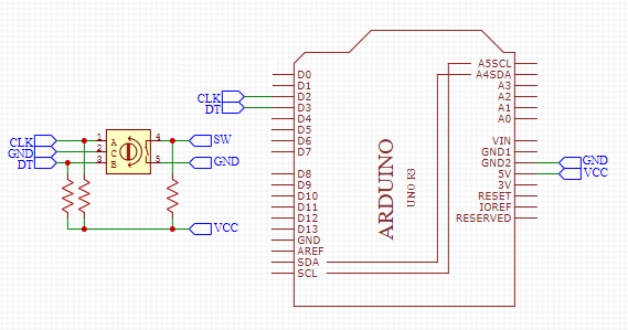
I've been testing my circuit (Arduino UNO) with a typical rotary encoder module for a week now.


and all of a sudden it started counting up and no matter I turn it clockwise or counter clockwise, it always counts up.
I checked my code, loaded some sample codes in the library i use, nothing changed.
Luckily I bough two of them, so I plugged the other module and it started to work.
So is my encoder gone bad? Are those so fragile to fail so soon? Just a week use. I'm pretty sure I did not abuse it that much for it to break so fast.
Anyone had this sort of a similar case?
Can anyone recommend me a good reliable encoder to use?
This is the test example I was trying.
/* Encoder Library - Basic Example
 * http://www.pjrc.com/teensy/td_libs_Encoder.html
 *
 * This example code is in the public domain.
 */

#include <Encoder.h>

// Change these two numbers to the pins connected to your encoder.
//   Best Performance: both pins have interrupt capability
//   Good Performance: only the first pin has interrupt capability
//   Low Performance:  neither pin has interrupt capability
Encoder myEnc(2, 3);
//   avoid using pins with LEDs attached

void setup() {
  Serial.begin(9600);
  Serial.println("Basic Encoder Test:");
}

long oldPosition  = -999;

void loop() {
  long newPosition = myEnc.read();
  if (newPosition != oldPosition) {
    oldPosition = newPosition;
    Serial.println(newPosition);
  }
}