I'm designing a board where many of them will be connected on a rs485 bus. However, I'm not sure how should I implement the bus termination and failsafe bias.
This is the schematics regarding the rs485 bus, is it done right? https://dl.dropboxusercontent.com/u/10930393/rs485.png
The board have two rj45 connectors, one input (comming from the previous board on the bus or from the master unit) and one output (going to the next board on the bus), the rj45 provides both power (+12v) and the rs485 lines.
Termination should be done through a jumper: I close the jumper on the last board on the bus)
I had develop a month ago some boards like the one you are creating and after assemble them I discover a problem about the R7 and R8 like in your schematic.The problem is when you connect more nodes you are putting resistors in paralel in these two resistors. Each node will decrese te value of R7 and R8 to half since the second node will be em paralel to this one.I'm my case the signal after connect the second node gets very low so my solution was lift the other resitors on the boards and just keep them in the first board.
The terminator resistor is fine.
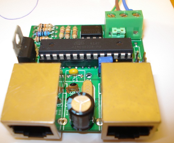
Here is my board fixed just to give you an idea
Isn't these resistors supposed to prevent unexpected readings when the line is disconnected?
I mean, suppose the cable that goes for input on the seccond board of the bus is broken... The A and B lines will now be fluctuating
I mean, suppose the cable that goes for input on the seccond board of the bus is broken... The A and B lines will now be fluctuating
No.Lets say you have just one board.The lines are fixed by the resistors on the first board as expected.If you connect the second board the output of the second board is still pulled high by the resistor of the first board and pulled down as well.If you keep the resistors in every board the side efect will reduce the resistor values half since they will be in paralel.
My conclusion is you can only have one par of resitors in the BUS.It happen the same with the terminator resistor.
Imagine what will happen if you active each terminator resistor on every board?
This will cause all resistors in paralel, that's why only the last one should be ON.
From Maxim application note:
"Failsafe Bias Resistors
When inputs are between -200mV and +200mV, receiver output is "undefined". There are four common fault conditions that result in the undefined receiver output that can cause erroneous data:
All transmitters in a system are in shutdown.
The receiver is not connected to the cable.
The cable has an open.
The cable has a short."
I think they mean that for each receiver on the system.
Anyway, if the failsafe resistors should protect the receiver when, for exemple, the cable is open, how could a resistor on the first device protect the second device if the cable between them is broken?
how could a resistor on the first device protect the second device if the cable between them is broken?
It can't. If the cable is broken all bets are off.
Note that most (all?) modern transceivers have fail-safe built in. How they do that without the parallel issues HugoPT was talking about I don't know, but they do. Probably some detection logic and FET switches or something.
BTW your FS resistor values are too low, I think abut 560R is typical. But as has been mentioned you can't have them on every node because they will all be in parallel, at least the ones to GND will be, not sure about the ones pulling high, depends on how everything is powered I think.
Yup, the failsafe bias resistors need to be higher than 120 ohms! Remember they act in parallel with the
termination load resistor, which may have to be increased in value to compensate. The supply at the failsafe
bias resistors needs to be decoupled at the resistors to provide a low-inductance return path.
The bus cable should match the termination impedance of course, so choose the right cable...
And yes, termination at each end of the cable, not anywhere else. If intermediate nodes might be unplugged
at some point you can add high-value (10k or so) bias resistors at those nodes so they failsafe when not connected
to the bus.
That chip doesn't have failsafe resistors built-in (that would compromise bus fanout), but
has a bias built in to the receiver for inputs less than +/- 200mV