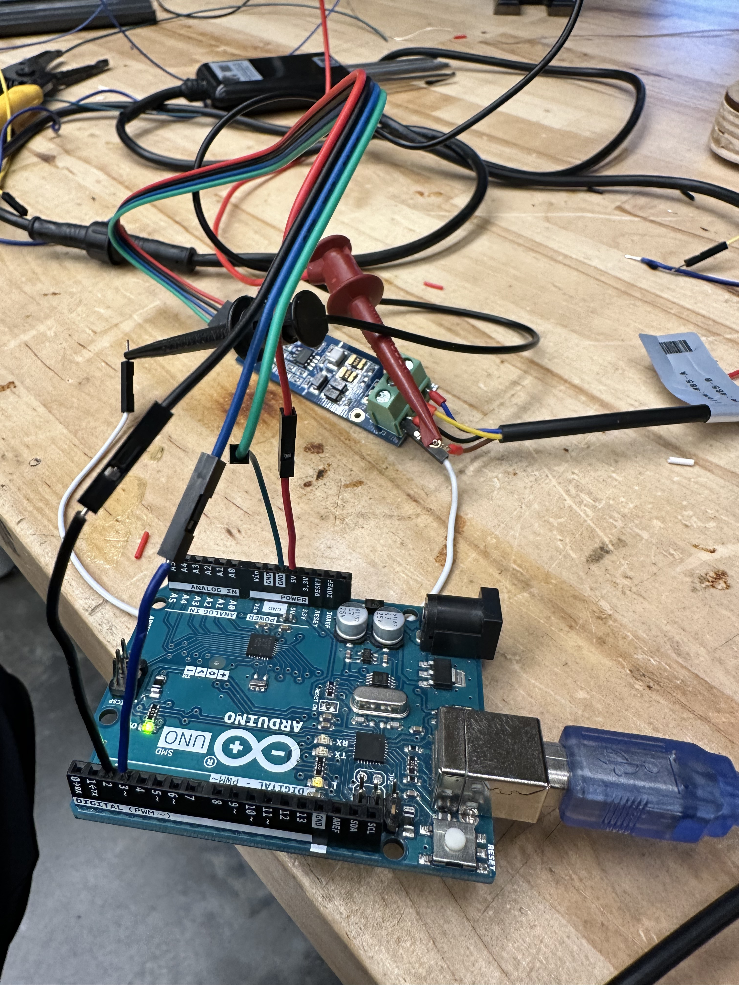
I'm working on a university capstone project and am running into some issues getting rs485 up and running.
the soil sensor has power to ground connectivity and so do all the pins coming off of the TTL Conversion board. I checked this with a multimeter
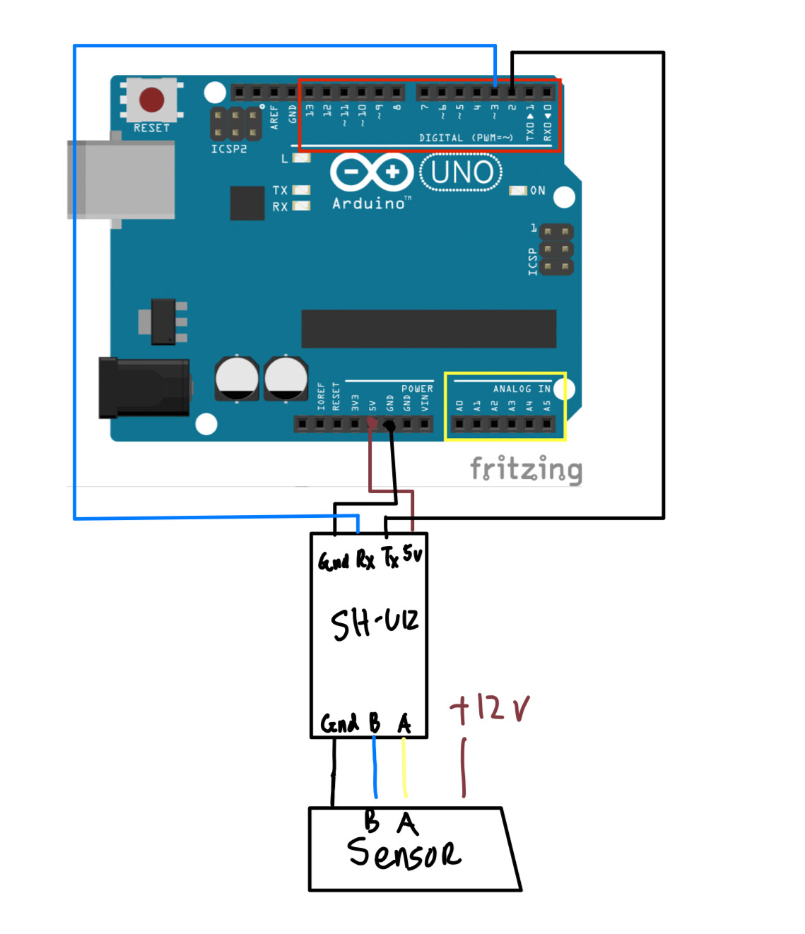
Components I am using:
Arduino UNO
DSD TECH SH-U12 RS485 to TTL 5V Board with MAX13487 Chip
https://docs.qq.com/doc/DUGtXbVhXZG1JckJq?newPad=1&newPadType=clone this is the link to the information. From amazon reviews I've read that there are cases where the TX/RX pins are reversed/the A and B Pins are reversed for the RS485 Side of things but I've tried that to no avail https://www.amazon.com/DSD-TECH-SH-U12-MAX13487-Raspberry/dp/B07B667STP/
5 Pin NPK Soil Sensor datasheet:https://cdck-file-uploads-europe1.s3.dualstack.eu-west-1.amazonaws.com/arduino/original/4X/d/f/5/df5ca5c3b195421786e97743713e97298e3eb638.pdf
https://www.amazon.com/Comprehensive-Corrosion-Resistant-Temperature-Conductivity/dp/B08M5PHQZ7/
This isn't the exact data sheet but the register mapping seem consistent across different manufacturers.
#include <SoftwareSerial.h>
SoftwareSerial mySerial(2, 3); // RX, TX
void setup() {
Serial.begin(9600);
mySerial.begin(4800); // NPK communicates at 4800 bps
}
void loop()
{
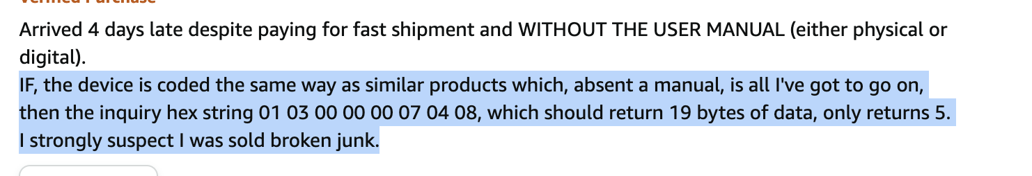
byte queryData[] {0x01,0x03,0x00,0x00,0x00,0x07,0x04,0x08};
byte receivedData[19];
mySerial.write(queryData,sizeof(queryData)); // send query data to NPK
delay(1000);
if (mySerial.available() >= sizeof(receivedData)) { // Check if there are enough bytes available to read
mySerial.readBytes(receivedData, sizeof(receivedData)); // Read the received data into the receivedData array
// Print the received data in HEX format
for (int i = 0; i < sizeof(receivedData); i++) {
Serial.print(receivedData[i], HEX);
Serial.print(" ");
}
Serial.println();
}
}
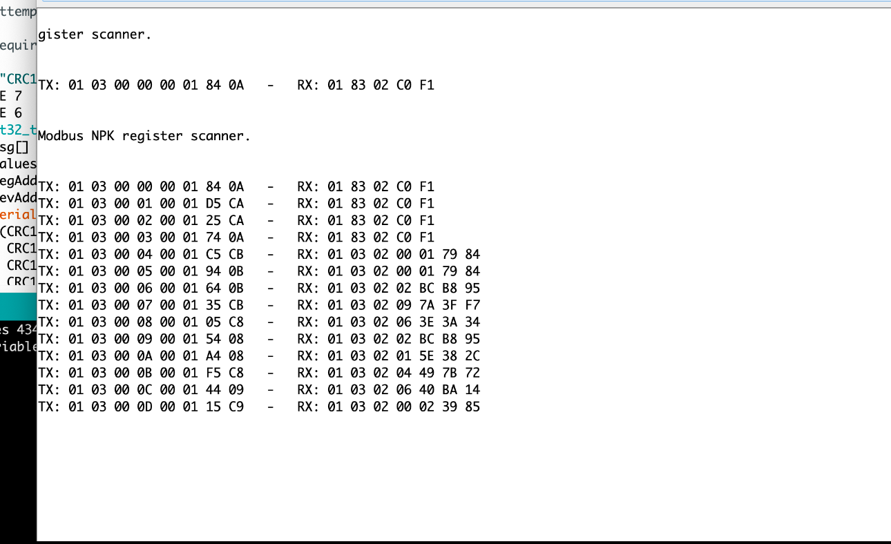
On this code I get an empty output. I tried changing around the TX/RX cables and the board changes from flashing RX to TX but its only ever just that one flash it never sends anything back and changes to TX/RX after sending the message.
I am using a 12 volt power supply to power the soil sensor it accepts 12-24V
Any advice on how to troubleshoot this further would be much appreciated