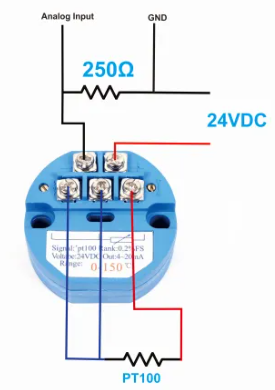
Hello, how are you, good afternoon, I need help to calibrate an RTD PT 100 sensor, I need you to give me an exact measurement on an Arduino or raspberry, in this case I will use an ARDUINO to capture the voltage, it is supposed to be a transmitter that gives 24 v, that's why I use the 250ohm resistor to scale it and be able to take a measurement from 0 to 5v. I had heard that measurements were taken and sent in Excel to graph them and then use a formula that makes the measurements align to the slope that is created with the measurements Is that correct? I want to make it as perfect as possible, it is for a project I hope you can help me. I attach the circuit. The trasmitter that i am using is a 0-200 C
Hello @jesuspuente112 - How are you? Please, refrain from creating multiple topics with the same subject. Would you flag this or your other topic for removal?
what is purpose of this blue round thing? i mean you can connect P100 directly to arduino, without BRT at all.
In order to calibrate anything, you need a standard to compare it to. You have not told us how you are going to calibrate the device you have in your hand right now. It's response will be different from some other device.
Your request is for a response curve, NOT a calibration.
1 Like

For example, if I need temperatures from 0 to 200, do I need to have an environment controlled at those temperatures? Because from what I understand, the sensor itself is not linear.
You can use the map() function to convert ADC readings to temperature.
Something like :
raw = analogRead(A0);
temperature = map(raw, 205, 1023, 0, 200);
(value 205 comes from the expected ADC reading for a current of 4mA.)
1 Like
i gonna try this when i am in the school. thank you:)
It's your project! How many different values can your temperature standard measure? Yes, you will need a closed enclosure that can hold and maintain the test temperature for both your device and your measurement standard. What accuracy are you attempting to attain for your device.
1 Like
"The map() function uses integer math so will not generate fractions, when the math might indicate that it should do so. Fractional remainders are truncated, and are not rounded or averaged."
Syntax
map(value, fromLow, fromHigh, toLow, toHigh)
If you want to get a result that has a decimal value, then you can always use 2000 as the 'toHigh' value and then divide by 10.
1 Like
You can, but you shouldn't. Resistance variation of an RTD is not as big as a thermistor. you could have a poor resolution without an RTD amplifier.
The blue thinghy seems like a poor choice, because now resolution depends on the A/D of the Arduino (~800 steps). A digital (15-bit) MAX31865 RTD100 amplifier would have been the best choice. I would only use that blue thinghy, with current loop, if the distance to the Arduino is significant.
Leo..
1 Like
If I want it for a closed environment, the problem is that right now I don't have something to be able to take temperatures from 0 to 200 degrees, I thought that the sensor could be calibrated without having to reach those temperatures, so to speak I'm like in the dark.
The photo shows a dedicated PT100-converter.
I expect it has compensation for the non-linearity of the PT100 element built in.
1 Like
What do you mean by significant distance? Loss of data?
I don't have it and I wanted to know if it could be done through code, the sensor only gives me voltages from 0 to 5 volts
Current loops (4-20mA) are mainly used in industrial environments, where the distance between sensor and processor can be the length of a factory.
The amplifier takes care of that problem.
Leo..
Then the best you can do is guessing. Why is calibration important to you? Is it worth the effort?
Not loss of data, it’s an analog system.
The PT100 works on resistance. At 0°C the resistance is 100Ω. At 200°C it’s 177Ω.
When the PT100 element is connected with long (or thin) wires, the resistance in the wires can cause misreading. The 3 wire system was invented to be able to compensate for that.
The 4 – 20mA system is also invented for use with long wires. Usually the output current is guaranteed up to 500Ω circuit resistance or more.
In your case you may assume that the accuracy of the converter is good (0.25%). The thing to worry about is the accuracy of the reference voltage of the ADC in the microcontroller.
The total system (PT100 + converter) was developed to avoid the need for calibration in the field.
Assuming the blue sensor amplifier is calibrated...
The accuracy of the 250 ohm resistor and, more important, the accuracy of the 5volt supply of the Arduino (assuming Uno R3) can throw things off.
If you are using the 5volt USB supply from a laptop/PC, and it (dynamically) varies 0.5volt, then your temp measurements will vary/jump 10%.
Consider a digital PT100 amplifier (post#12), so you don't have to worry with the inaccuracy of the Arduino A/D.
Leo..
This topic was automatically closed 180 days after the last reply. New replies are no longer allowed.