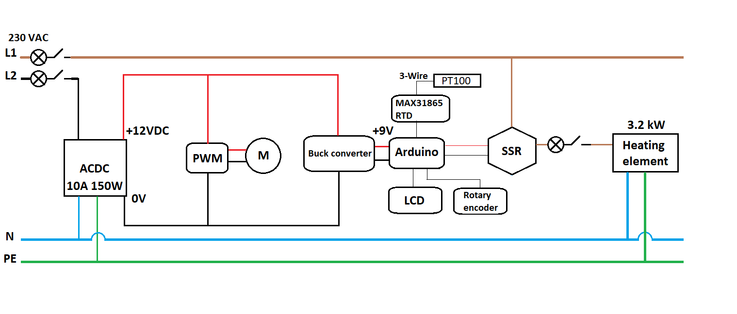
I'm working on an automatic beer brewing project. I have built a control box that basically consists of:
SSR relay
3.2kW heating element
Arduino to control heating element w/ PID
12V 150W PSU
12V motor
PWM box to control the motor
MAX31865 RTD
PT100 temp sensor
See attached picture for the circuit diagram.
Basically what the program does is it reads the temperature of water in a kettle and outputs a signal to the SSR to heat the water according to the PID algorithm to reach the setpoint.
However, whenever I run the motor (it agitates the water) the temperature reading stop working. It recovers once I turn the motor off. Not that the motor doesn't actually have to start spinning for the sensor to go haywire. Just as soon as there is some current going to the motor the sensor is disturbed.
What I see when I probe the circuit with a volt meter:
Supply voltage at any point in the logic circuit seems stable regardless of the motor running or not.
Voltage on the RTD PCB when measuring between GND and SDO pins is in the mV range. When the PWM to the motor is turned up, the voltage between these pins start to rise until it reaches 5V, which I do not think is supposed to happen since SDO = Serial Data Out. Also the voltage between the PT100 wires goes from 0.25V to 0 when I turn the PWM on.
I have tried to shield the RTD board by putting it in a metal bucket. I have also tried to power the logic circuits with a separate PSU (5V USB charger) through the USB connector on the Arduino instead of using the PSU that drives the motor.
I can take the sensor out of the kettle and try. The motor and the sensor are only in contact through the water in the kettle however.
I do not have any diode connected to the motor. I always assumed the pwm controller took care of that. Also the problem occurs before the motor even starts rotating which is why I assume it is not due to current generated by the motor.
I have been away a few days and just came back to test the things you guys suggested among other things.
I separated the temperature probe from the kettle as suggested. No change.
I put a diode over the motor leads. No change.
I drained the kettle of water. When the water level went below the stirring arm that is connected to the motor, the problem went away.
I filled the kettle again. I thought it was a problem with the ground connection of the motor so I connected a wire on different places on the motor housing/shaft to different places on the kettle and ran the motor. No change. I also checked the P.E connection to the kettle, all good.
I then went on to check the P.E connection on the 230VAC side of things. Everything seems to be connected as it should.
I measured the voltage between P.E and +12V. This is where I saw some strange behavior. There was a constant 25mV showing here when the system was idle. When turning up the PWM the voltage started jumping between 0-ish and up to a level corresponding to the voltage the PWM was supplying to the motor.
Any ideas how I can fix this is greatly appreciated. Thank you!
The 25mV when idle was a bit of a fluke, probably due to the potentiometer on the PWM box not going back to 0 properly. When I measured again today there was 0 voltage between +12V and P.E when the motor was idle. But still varying voltage when running the motor.
I measured the current between the stirring shaft and the kettle and I got around 80µA when the motor was running at half speed.
I also tried once more to use a separate power source for the Arduino. This didn't work before, but now it seems like it does.
I checked the voltage between the motor leads and the motor housing. The housing seems to have a lower potential than both motor leads. Running the motor at 3V showed 5V between the housing and the + lead. I tried connecting the housing to the GND lead. No change other than the motor running slower.
I used a separate power supply for the Arduino. I disconnected everything from the kettle so there is no connection between the motor or kettle and the Arduino. I took the motor off the kettle and held it while running. As soon as I touched the motor housing or shaft to anything grounded, the temperature sensor started acting up again.
I think I have solved the problem. There were actually two issues.
The temperature probe has a metal sleeve. When this touched either the kettle or the bench (metal bench), electrical noise from the motor would disturb the signal through the sleeve. I'm going to add a rubber sleeve on top of the metal sleeve to isolate it.
The second problem was noise from the PWM output. Since everything is in a box, when the output from the PWM reached a certain threshold the Arduino would pick up the noise from the power cables nearby. I added a metal sleeve to the PWM output cables. At first however, the sleeve made no difference. Finally when I grounded the sleeve to P.E. the problem went away.