Run an UNO and a 12V DC motor by one battery + other components? (Solar tracker)

Hello guys, this is my first time posting here! I am about to built a single axis solar tracking device for a project as part of my studies. There are a few questions that I have regarding the power supply of the Arduino UNO board and the DC gear motor. This is my first serious project ever, my knowledge on electronics is very basic.

I would like to use only one battery to give supply both to Arduino UNO and DC gear motor (12V). The DC gear motor will be run in both direction according to the LDR sensor readings.

Motor Specification:
36GP permanent magnet DC planetary gear motor
Voltage: DC 12.0V
Output speed: 25rpm
Maximum torque: 45kg.cm
No-load Current: 220mA (Max)
Stall Current: 3000mA (Max)
Stall Torque: 45.0kg.cm (Max)
Rated Torque: 10000g.cm
Rated Current: 560mA (Max)

For the moment I have as a part that might be useful an L298N motor driver.
My questions are:
0) first of all is it possible?

  1. What type of battery should I use (Construction type, Volt, mAh etc)...it should be rechargeable and able to operate for a week or more.
  2. What other components should be used in order to achieve the use of one battery by both UNO and Motor.
  3. Do you thing i should use a relay between motor and circuit or just a motor driver would be fine?

If you have any ideas or you would like to ask me something in order to understand better the construction please ask me and I 'll try to explain. Thank you for your time!

p.s. i attached the L298N conection with UNO diagram..

L298N_ARDUINO_CONNECTION_Diagram_18591_1625300664395363_1587098407476938529_n.jpg

Cannot see why that should not work.

For the current needed, if you have the space I would go for a leisure / caravan / deep cylce lead acid battery, though many other choices.

The Arduino jack socket can run off the same 12V dc but many suggest thats a little high to avoid overheating the onboard regulator, depending on what else the Arduino is driving.
You could use an external regulator instead, down to 7v to 8v or even 5v direct.

The L298 datasheet offers plenty of info, but suggest you look at the Arduino L298 motor shield schematic and create a current sense circuit as its quiet easy to blow its output transistors.

An alternative module, the LMD18200 is said to be much more protected, many on ebay

The L298N driver can't handle the 3 ampere motor stall current, which the motor will briefly draw every time it starts up. You will need a modern motor driver, like this one.

You need to know the average current draw of your project, while in typical operation, in order to determine the required battery capacity. A rough estimate for the hours of operation would be (battery capacity in mAh)/(average mA).

Happy new year! Thank you so much for your messages! I saw them very late, I thought I would receive an email, I am sorry for the late response...Anyway, I am really thankful because with some keywords that you mentioned you helped me do some research for things that I didn't know.

ricky101:
Cannot see why that should not work.

Ok that's good news, I was just wondering how am I going to do it...am I going to just use four wires (2 for the DC motor and 2 for the Arduino) that are going to be connected straight on to the battery poles? Is this ok? Or it is necessary to use a something like a power supply module?

ricky101:
The Arduino jack socket can run off the same 12V dc but many suggest thats a little high to avoid overheating the onboard regulator, depending on what else the Arduino is driving.
You could use an external regulator instead, down to 7v to 8v or even 5v direct.

Here says that Arduino UNO has a Minimum input limit at 6V and the recommendation is at 7V...so i thought that a Regulator LM7807, which is giving 7V, would be a good choice to use between the 12V battery and the Arduino (with the Barrel jack), just to be sure that the on-board linear Regulator is not going to raise temperature. Do you think is too much or is it ok?

ricky101:
The L298 datasheet offers plenty of info, but suggest you look at the Arduino L298 motor shield schematic and create a current sense circuit as its quiet easy to blow its output transistors.

jremington:
The L298N driver can't handle the 3 ampere motor stall current, which the motor will briefly draw every time it starts up.

After looking closer to L298N module, it has 2A Drive current for continuous current draw but for instantaneous current draw has a maximum limit of 3A. So my thought is that since the DC Gearmotor is going to operate just for a few seconds each time and of course 3A is the Stall current, which means that probably the construction is not going to reach that stress level for more than 2 seconds, I am going to give it a shot and see if it's working.

ricky101:
An alternative module, the LMD18200 is said to be much more protected, many on ebay

jremington:
You will need a modern motor driver, like this one.

LMD18200 though seems like a much better choice than L298N, but I have so little time that if I order it now it will take about a month to receive it. MC33926 Motor Driver Carrier that jremington suggested seems more professional but again it will be my last choice (if the others don't work) as it costs triple the price against the other two.

I stumbled upon this website and I found out that a 3rd option to include to DC motor controlling would be to use a 2 channel relay board – module like this one. My only concern about this option is the speed i.e. the time that the system will take to switch ON and OFF after the photoresistors measurements. Could such problem exist, Do you think that this could be a major problem? In case of using relay how am I going to control the speed of the motor (There is no PWM)? Will i have to control it by lowering the Voltage with a regulator or a potentiometer?

jremington:
You need to know the average current draw of your project, while in typical operation, in order to determine the required battery capacity. A rough estimate for the hours of operation would be (battery capacity in mAh)/(average mA).

About the power consumption: the battery will supply with power two loads, 1) Arduino (and all that is on it), 2) the mentioned DC Gearmotor.

  1. Arduino will have connected on it:
  • 2 simple photoresistors: maximum power consumption for each is 100mW (how much is this in mA?)
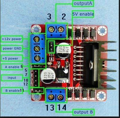
  • A Motor driver module: If it is “L298N Dual H-Bridge” it has logical current draw 0-36mA, (the current for the operation of the board is different?)
  • Or a 2 Channel Relay board: 15 – 20mA for each channel (the current for the operation of the board is different?)

Also Arduino by it self needs some power to operate, for example to run code, how do i calculate that operation consumption?

  1. The DC Gearmotor will be connected either to the “L298N Dual H-Bridge” or the 2 channel relay:

Relay is in fact switch which means that the Motor will draw current as long as the switch remains ON, I don't know for how long though, lets say for 1-2 seconds every 3-5 minutes. 3A is the maximum current draw. How do I calculate the power consumption with such information?
Is it also going to be the same with the motor driver or the DC motor will draw also current from the battery when the motor is not operating?

Sorry for the very long text, any comment and correction is of course welcome!

Hi,

Check your profile settings to enable the receive Notifications box/s

Your two lines to the battery should be fitted with suitable fuses and a switch to isolate the power if things go wrong as the batterys power can cause a lot of damage.

You can use a 7807, though not a popular / stocked device and it will probably need a heatsink and some small capacitors.

Probably a lot simpler if you can buy a buck converter locally, preferably the type with a blue trimmer.
http://www.ebay.co.uk/itm/LM2596-DC-Buck-Step-Down-Voltage-Adjustable-Converter-Power-Module-Regulator-/282306624241?hash=item41bac93af1:g:xikAAOSwj85YPEAi

The L298 has 2 separate drivers, so if you are only using 1 driver, then follow the datasheet and connect it up Bridge mode, so it doubles the load it can handle.

The L298 is not well protected against output short circuits and will readily blow, so you must fit a fuse in the motors line to protect it.

What it really needs is a current sense resistor feeding back to the Arduino so it can shut the L298 down if an overload happens.

If you look up the Arduino Motor Shield which uses the L298 you can see the current sense resistors and the Amplifiers needed to create a suitable voltage for the Ardunio.

Are you using a Motor Shield schematic , L298 module or building your own with a L298 chip ?

ricky101:
Your two lines to the battery should be fitted with suitable fuses and a switch to isolate the power if things go wrong as the batterys power can cause a lot of damage.

You can use a 7807, though not a popular / stocked device and it will probably need a heatsink and some small capacitors.

Probably a lot simpler if you can buy a buck converter locally, preferably the type with a blue trimmer.
http://www.ebay.co.uk/itm/LM2596-DC-Buck-Step-Down-Voltage-Adjustable-Converter-Power-Module-Regulator-/282306624241?hash=item41bac93af1:g:xikAAOSwj85YPEAi

So if i am understanding right you are saying that i can use a buck converter and a Switch (to have control over the circuit) between battery and Arduino to protect the Arduino..it is like an adjustable regulator right?

By typing 7807 on google nothing useful comes up as a result...what is a 7807?

Sorry i didn't make it clear i will use an L298N Module, do you thing that it needs extra protection? like fuse? Or a current sense resistor, as you mentioned?

@ricky101 Thanks for all the new info! Still though very unfamiliar with some terms...trying my best

AntonisL:
So if i am understanding right you are saying that i can use a buck converter and a Switch (to have control over the circuit) between battery and Arduino to protect the Arduino..it is like an adjustable regulator right?

Yes, thats right, but the switch is before the buck converter and the power line to the motors so if anything goes wrong you can cut the power to everything. Also just before or after the switch you want a fuse.

By typing 7807 on google nothing useful comes up as a result...what is a 7807?

The LM 7807 you mentioned earlier in your entry #3

Sorry i didn't make it clear i will use an L298N Module, do you thing that it needs extra protection? like fuse? Or a current sense resistor, as you mentioned?

Yes , have used that board, you will need a fuse on the output line to the motor so if it shorts /jams and overloads the fuse will blow, hopefully before the L298.

That board is not fitted with current sense resistors but can be added, though perhaps consider that later.

@ricky101 Thanks for all the new info! Still though very unfamiliar with some terms...trying my best

Not a problem, we all started at the begining :slight_smile:

:slight_smile:

So i will have to use a fuse before the buck converter and also between the L298N Board and the Motor...i have some questions regarding that part.

  1. What are the creteria to choose a fuse? Current limit? As i can see there are many types to choose from, could you please tell me an example?

  2. Will the buck converter and all the extra components that i may add, draw more current from the battery?

  3. For the Driver/Motor side, i was thinking that i could use something like automatic switch that will turn off when the current reach a limit...do you think that i could cheaply do something to achieve this? Or it is just too much?

  4. The use of a diode between the driver's output and the motor, is it a good idea? instead of a fuse? Or maybe both is better? I though that i could do that just to be sure that if the DC motor return any high current will not reach back the L298..

So just to make something clear in my mind: The battery will provide current to Arduino UNO and Motor according to the needs of each? Is it true that electricity has the property to flow only through the part of the circuit which has the lowest resistance? Is there anything to take under concideration in that power supply part?

Any link about "short/jam" that you mentioned would be very useful, i can't find what jam is...

From an electronic point of view a standard fuse is a crude device, however its simple and cheap to use.

I would configure your design as the picture shows, with a 2A fuse to protect the L298 and the motor which should cope with the start up surge, but blow before any high stall current was encountered.

A switch and 3A fuse protect the whole circuit.

Short /Jam - was meaning a short circuit of the motor, or the motor physically being jammed when running, so causing a heavy stall current

The buck converter and the Uno etc will only add a little extra current compared to the heavy current of the motor, without measuring, would say well below 100ma.

Your automatic current overload switch would be as described earlier, like the Aduino motor shield used, as that is the fastest acting, lowest cost method.
However as said before, thats an extra circuit and programming and can be added later if needed.

Your diode in the output idea, you have a bit of learning to do there about the flow etc etc.
The power will flow More through the lower resistance, but still flows though all other higher ones.

I'm not a science teacher, but suggest you look up the basic theories on some of the better web and ytube tutorials, though its not essential to know to get your project working now, things will more than likely start to make more sense as you get building.

Thank you very much for the image and effort! I really appreciate it!

You are right, things will make more sense when i will start building the circuit...i am just a little afraid of accidentally frying stuff cause then i will have to buy them again :stuck_out_tongue: , that's why the many questions..

The L298N boardthat i bought says that it has 2A maximum drive current (continuous) and a maximum of 3A (instanteneous)... @jremington mentioned in previous message that:

jremington:
The L298N driver can't handle the 3 ampere motor stall current, which the motor will briefly draw every time it starts up.........

So everytime it starts up will draw 3A for a few ms, isn't the fuse going to blow when the motor starts?
You mentioned in the message #4 that "The L298 has 2 separate drivers, so if you are only using 1 driver, then follow the datasheet and connect it up Bridge mode, so it doubles the load it can handle." i guess i can't do that on a ready board right?

We all blow up parts now and then :smiling_imp: it more a case of protecting the expensive parts like your motor.

The L298 is the most likely part to be damaged, but those little modules are so cheap, I can now buy them locally for almost the same price as the far east ones.

How much current your motor takes at start up is always a difficult one and not something you can check with the average DVM.

That why you will have to experiment with the fuses, if it blows a 2a at start up then try a 2a Slow blow type, designed to handle such surges, if not they try 2.5 a

If you look at the L298 datasheet you will see you are using just one of the two H bridge sections as shown in Fig 6.

Just below in fig 7 it shows how you can parallel the two sections to almost double the current handling and should make it a more robust driver for you.

Notice how the inputs and output pins are connected, it can all be done from the 4 Input and 4 Output edge connectors of the board.

http://www.mouser.com/ds/2/389/l298-954744.pdf

haha yes blowing up parts is knowledge i guess : P

That's what i am going to do i will just use some fuses for testing!

OK so i can drive maximum of 4A if i connect both outputs in parallel...but how can i do that, with the very basic knowledge i have, the datasheet doen't really help. Anyway once i start building it i guess i will figure it out how..

Thanks again for your time and effort @ricky101 :wink:

Below is a picture of a L298 module like mine and I have added the Pin numbers of the L298 chip to the modules input and output connectors.

If you see the Fig 7 on the datasheet it shows which Pin / Edge connectors you must join up to make it work in bridged mode.

l298.jpg

:slight_smile: Perfect! That seems super easy! In the near future i will post here the results and pictures of the connections, in case someone needs it!