http://www.youtube.com/watch?v=o05egiiNwnY
Nice.
However I changed my mind and decided to make letters with LED's so I now have 11 Letters spelling the word "Looping Star". The maximum amount of LED's per letter is 10 however most of them contain less LED's
That's okay. It's the total current per 'string' (all controlled by one pin) that matters.
11 Transistors and put the LED's in series.
That would work, be careful that you don't try to put too many LEDs in series. It's a bit of a pain to wire up transistors compared to anything in a DIL socket, but once done, it's done, so "have at it" and have fun.
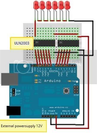
I'll use a 500mA 12V powersupply which should be enough for the LED's to work all at the same time
Not sure exactly what you mean.
The foward voltage drop of ordinary LEDs is about 1.7V.
The transistor will drop about 0.7V too
So the maximum number of LEDs you could drive from 12V is
(12-0.7)/1.7 = 6
It gets worse for other LED colours, so check that it's okay.
If there are 11 letters, with say, 2 sets of series-conneted LEDs each, then the total current the LEDs can draw is:
500mA = (11 * 2 sets of LEDs)
so one set of LEDs could draw:
500mA / (112) = 22mA
If you are running the Arduino from the same power, allow (guess) 100mA
(500mA-100mA) / (112) = 18mA
I'd be conservative and reduce it by 50-100% to make sure everything is well within safe limits.
So, as long as you don't have more than 6 LEDs (or whatever the forward voltage drop is) in a series it'll be okay. It's okay to drive several series-connected sets of LEDs from one transistor. You should protect each Arduino output pin with a small resistor between it and the transistors base. That is the another nice thing about the ULN280x family, that is already implemented internally.
However I'm not entirely sure if this will work, looking at the Arduino Duemilanove datasheet it doesn't say anything about the current coming from the Vin pin. Is this one also limited at 40mA or would it be the same as the power supply, capable or 500mA?
I'm not sure I understand.
Is the plan to plug the 12V 500mA power supply into the external power socket?
Then take the Vin to the LEDs and transistors?
You can connect power to the external power socket (best as it is protected by a diode) or the Vin pin (not as good as a reversed voltage may damage the board) to power the Arduino.
If you also take the power from Vin to the LEDs+resistors, you'll be going through the Arduino's reverse voltage protection diode. It depends a little bit on the board. AFAIK, most are rated to handle more than 500mA (I use 1A or more on my designs because diodes are very cheap, and who knows what folks will hang on Vin 
But you might want to double check.
Vin is not restricted in the way a digital output pin from the Arduino. So it is only the diode and electrical properties of the Vin pin that should matter. Ordinary pin headers and pins should be okay with more than 0.5A.
So, if I have understood, you should be fine.
HTH
GB