Hello, i want to connect my esp32 cam to my arduino uno through the rx tx pins. but, currently my arduino uno have l293d motor driver shield attach to it (to control servos and motor), and it occupied the rx tx pins, how should I deal with this?
Which L293D driver shield?
Note that connecting anything to Rx and Tx will interfere with the upload to the Uno.
If it has headers, you can use the Rx and Tx pins on the header. Some shields also have a connection for a Bluetooth module; you might be able to use that.
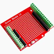
You can also use a screw shield between the uno and the driver shield; e.g.
DPin-7 and Din-8 of the UNO are free. You can use these these pins as Software UART Port and connect your ESP32-CAM's Serial Port with them.
Take two Male-Female jumpers; cut the Male sides; take out about 1/4" insulation; tin the bare wires and nicely solder them on DPin-7 and DPin-8. Connect the Female sides with Male pins of the CAM Module.

hello, this is my l293d driver shield

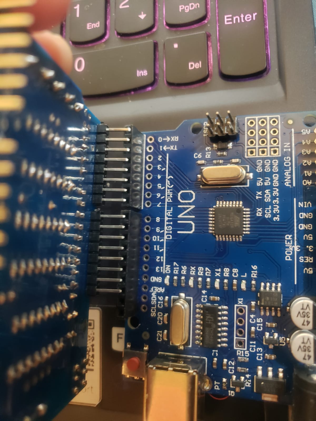
from my experience, the shield doesn't interfere with the uploading process even tho it occupied the rx tx pins, so it doesn't actually use those pins?
Free in this case means "electronically free" also known as "not used" by the shield.
I think that this is the schematic: Adafruit_Motor-Shield-v1/mshieldv12schem.png at master · adafruit/Adafruit_Motor-Shield-v1 · GitHub; A0 to A5 are free for SoftwareSerial.
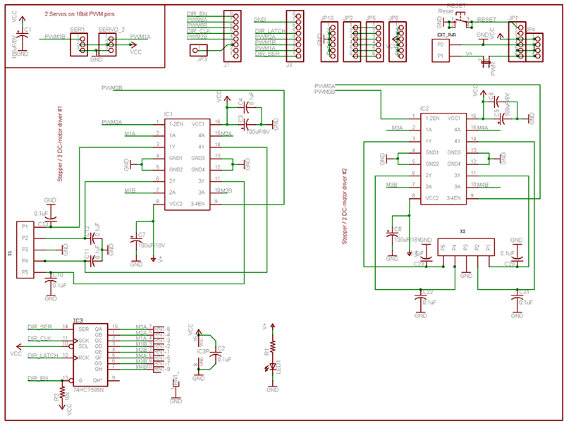
Please, check the schematic of this link; you will see that DPin-7 and DPin-8 are not used by the Motor Driver Board.
ah i see, if you don't mind could you give me step by step on how to connect esp32 cam to my arduino? I'm sorry I just started doing these for school projects so I don't have experience
That is not the Adafruit shield that @oddduckk showed in the image.
This is schemtaic to which I have referred OP, and this schematic belongs to a 3-chip (2xL293D and 1x74HC595) version Board. I have exactly same Board as the OP has.

I have no idea about the ESP32 CAM, it probably has multiple serial ports.
For the Uno side, see https://docs.arduino.cc/tutorials/communication/SoftwareSerialExample/. Note that is uses pins 2 and 3, you will have to change that to e.g. A0 and A1.
Change
SoftwareSerial mySerial(2, 3); // RX, TX
to
SoftwareSerial mySerial(A0, A1); // RX, TX
And connect those pins to the ESP32 CAM; you will need a voltage divider between the Tx pin of the Uno in above and the Rx pin of the ESP32 CAM (as the latter is a .3V device).
It's easy for OP to check using a multimeter. And to play it safe (![]() ), I would use A0 and A1.
), I would use A0 and A1.
Yes! A0 and A1 are also free pins.

From this video , It show we can solder. you and I are facing same problem !!
This topic was automatically closed 180 days after the last reply. New replies are no longer allowed.