Hello. I was interested in continuing an older thread about SAMD21 TC PPW to which many of you have already responded, but it is old and now locked.
I am new to SAM21 SoCs - more experience with STM32 and smaller PIC12/14/16 SoCs. So I will probably ask a question that has already been answered; my apologies in advance.
Briefly, I used code once posted by MartinL in Arduino Zero TCC Capture - Arduino Zero - Arduino Forum to get started with capturing a fairly slow wave, but with millisecond accuracy. I changed the dividers and prescalers to step TC3 at 10000 Hz, and wired a 555 to generate test patterns on the input pin. MartinL's code got some very nice results (Thank You, MartinL).
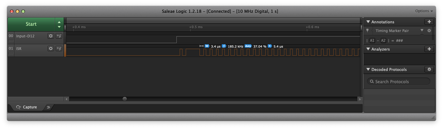
But I noticed something I cannot explain. I instrumented the ISR ( TC3_Handler() ) by having it toggle a pin when invoked. I see that the ISR is being invoked continuously when the input (the waveform) pin is high. After the wave's rising edge, the ISR fires and I see the time taken to sync-read the counter to complete the previous cycle. It returns, but then runs again in 3us - as fast as it can, but there is nothing to do. MC1/MC0 are not set in INTFLAG.
Once the input waveform falling edge arrives, the ISR is not called again until the next rising edge. So I cannot figure out why the handler is being triggered during the pulse phase (high level) of the input.
I added more instrumentation and I see that TC3 INTENA is only what I expect, MC1/MC0. When the ISR is entered over and over, INTFLAG is nothing but SYNCRDY. But that interrupt is not ENAbled, and I even added a write to to INTCLR to make sure it was masked.
Being new to this level of Arduino coding (I've always used it only at the high level before), there's a lot BSP/HAL under here that I have yet to learn. Can anyone shed light? In my case, this could consume 30-40% of the CPU and affect power savings - so, I'm curious 
Images attached, and code below.
Thank you for your time.
-wt


// Setup TC3 to capture pulse-width and period
volatile boolean periodComplete;
volatile uint16_t isrPeriod;
volatile uint16_t isrPulsewidth;
uint16_t period;
uint16_t pulsewidth;

const int     scopePin = 13;

void TC3_Handler(void);

void setup()
{
  Serial.begin(115200);                  // Send data back on the Zero's programming port
  while (! Serial);                      // Wait for the Serial port to be ready

  pinMode(scopePin, OUTPUT);
  digitalWrite(scopePin, LOW);

  REG_PM_APBCMASK |= PM_APBCMASK_EVSYS;     // Switch on the event system peripheral

  REG_GCLK_GENDIV = GCLK_GENDIV_DIV(75) |   // Divide the 48MHz system clock by 75 = 640,000Hz
                    GCLK_GENDIV_ID(5);      // Set division on Generic Clock Generator (GCLK) 5
  while (GCLK->STATUS.bit.SYNCBUSY);        // Wait for synchronization

  REG_GCLK_GENCTRL = GCLK_GENCTRL_IDC |           // Set the duty cycle to 50/50 HIGH/LOW
                     GCLK_GENCTRL_GENEN |         // Enable GCLK 5
                     GCLK_GENCTRL_SRC_DFLL48M |   // Set the clock source to 48MHz
                     GCLK_GENCTRL_ID(5);          // Set clock source on GCLK 5
  while (GCLK->STATUS.bit.SYNCBUSY);              // Wait for synchronization

  REG_GCLK_CLKCTRL = GCLK_CLKCTRL_CLKEN |         // Enable the generic clock...
                     GCLK_CLKCTRL_GEN_GCLK5 |     // ....on GCLK5
                     GCLK_CLKCTRL_ID_TCC2_TC3;    // Feed the GCLK5 to TCC2 and TC3
  while (GCLK->STATUS.bit.SYNCBUSY);              // Wait for synchronization

  REG_EIC_EVCTRL |= EIC_EVCTRL_EXTINTEO3;                                 // Enable event output on external interrupt 3
  //EIC->CONFIG[0].reg |= EIC_CONFIG_SENSE3_BOTH;                           // Set event detecting changes to level

  attachInterrupt(12, TC3_Handler, HIGH);                                 // Attach interrupts to digital pin 12 (external interrupt 3)

  REG_EVSYS_USER = EVSYS_USER_CHANNEL(1) |                                // Attach the event user (receiver) to channel 0 (n + 1)
                   EVSYS_USER_USER(EVSYS_ID_USER_TC3_EVU);                // Set the event user (receiver) as timer TC3

  REG_EVSYS_CHANNEL = EVSYS_CHANNEL_EDGSEL_NO_EVT_OUTPUT |                // No event edge detection
                      EVSYS_CHANNEL_PATH_ASYNCHRONOUS |                   // Set event path as asynchronous
                      EVSYS_CHANNEL_EVGEN(EVSYS_ID_GEN_EIC_EXTINT_3) |    // Set event generator (sender) as external interrupt 3
                      EVSYS_CHANNEL_CHANNEL(0);                           // Attach the generator (sender) to channel 0

  REG_TC3_EVCTRL |= TC_EVCTRL_TCEI |              // Enable the TC event input
                    /*TC_EVCTRL_TCINV |*/         // Invert the event input
                    TC_EVCTRL_EVACT_PPW;          // Set up the timer for capture: CC1 period, CC0 pulsewidth

  REG_TC3_READREQ = TC_READREQ_RREQ |             // Enable a read request
                    TC_READREQ_ADDR(0x06);        // Offset of the CTRLC register
  while (TC3->COUNT16.STATUS.bit.SYNCBUSY);       // Wait for (read) synchronization
  REG_TC3_CTRLC |= TC_CTRLC_CPTEN1 |              // Enable capture on CC1
                   TC_CTRLC_CPTEN0;               // Enable capture on CC0
  while (TC3->COUNT16.STATUS.bit.SYNCBUSY);       // Wait for (write) synchronization

  //NVIC_DisableIRQ(TC3_IRQn);
  //NVIC_ClearPendingIRQ(TC3_IRQn);
  NVIC_SetPriority(TC3_IRQn, 0);      // Set the Nested Vector Interrupt Controller (NVIC) priority for TC3 to 0 (highest)
  NVIC_EnableIRQ(TC3_IRQn);           // Connect the TC3 timer to the Nested Vector Interrupt Controller (NVIC)

  REG_TC3_INTENSET = TC_INTENSET_MC1 |            // Enable compare channel 1 (CC1) interrupts
                     TC_INTENSET_MC0;             // Enable compare channel 0 (CC0) interrupts
  REG_TC3_INTENCLR = TC_INTENCLR_SYNCRDY;

  REG_TC3_CTRLA |= TC_CTRLA_PRESCALER_DIV64 |     // Set prescaler to 64, 640kHz/64 = 10kHz
                   TC_CTRLA_ENABLE;               // Enable TC3
  while (TC3->COUNT16.STATUS.bit.SYNCBUSY);       // Wait for synchronization
}


void loop()
{
  if (periodComplete)                             // Check if the period is complete
  {
    noInterrupts();                               // Read the new period and pulse-width
    period = isrPeriod;
    pulsewidth = isrPulsewidth;
    periodComplete = false;                       // Start a new period
    interrupts();

    Serial.print(period);                         // Output the results
    Serial.print(F("   "));
    Serial.println(pulsewidth);
  }
}


void TC3_Handler()                                // Interrupt Service Routine (ISR) for timer TC3
{
  digitalWrite(scopePin, HIGH);

  // Check for match counter 0 (MC0) interrupt
  if (TC3->COUNT16.INTFLAG.bit.MC0)
  {
    REG_TC3_READREQ = TC_READREQ_RREQ |           // Enable a read request
                      TC_READREQ_ADDR(0x18);      // Offset address of the CC0 register
    while (TC3->COUNT16.STATUS.bit.SYNCBUSY);     // Wait for (read) synchronization
    isrPeriod = REG_TC3_COUNT16_CC0;              // Copy the period
    periodComplete = true;                        // Indicate that the period is complete
  }

  // Check for match counter 1 (MC1) interrupt
  if (TC3->COUNT16.INTFLAG.bit.MC1)
  {
    REG_TC3_READREQ = TC_READREQ_RREQ |           // Enable a read request
                      TC_READREQ_ADDR(0x1A);      // Offset address of the CC1 register
    while (TC3->COUNT16.STATUS.bit.SYNCBUSY);     // Wait for (read) synchronization
    isrPulsewidth = REG_TC3_COUNT16_CC1;          // Copy the pulse-width
  }

  digitalWrite(scopePin, LOW);
}