Excuse my newbie schematic, but I have recently assembled this circuit with an MPU6050 chip pulled out of some breakout I found. I connected it to an UNO and scanned for I2C devices and the scanner kept getting stuck when I had it connected. The weird thing is that for literally one second it showed up once and I was never able to get it to show up again. I got a brand new chip, swapped it in, and still nothing...
When I was testing it, I didn't have anything else hooked into the circuit. The Xiao that is in the schematic wasn't in either and I just soldered leads to the pads for testing.
The MPU605 is a 3.3 volt device and it should not be directly connected to a 5 volt UNO.
The UNO 5 volt SDA and SCL should be connected via a level shifter.
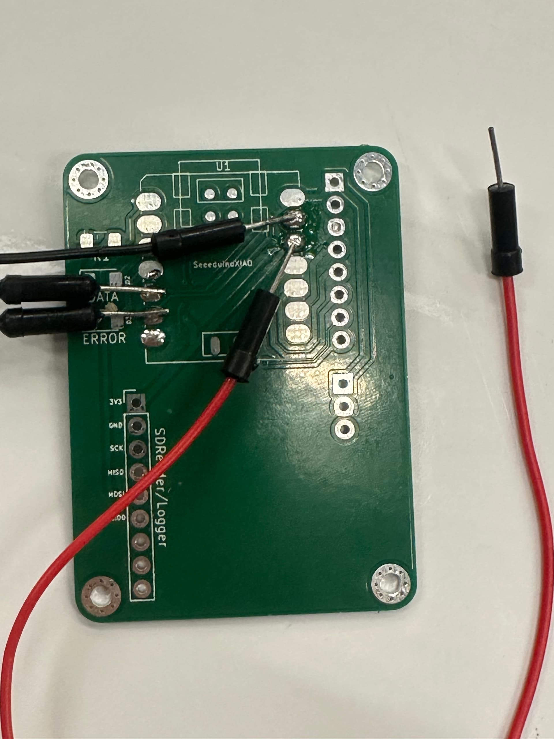
Blue, here is the front and back of the PCB in real life and in kicad. I noticed that the middle pad directly under the chip is missing on my PCB. Could that be a make-or-break?
The design looks good. However, improper soldering on the MPU6050 could cause intermittent connections or shorts. Take a multimeter and check for unwanted short circuits or broken traces.
I dont believe the module i was basign this design off of has a level shifter. Strange however, I tested that module stripped of pretty much everything but the things i have on my board and that one worked just fine... It seems like it gets away with using just the resistors on the SDA and SCL lines.
Thank you for the confirmation aliarifat! I will double and tripple check the soldering to verify everything is in order. This one specifically i think i will just resolder with a hotplate anyways to get better connections hopefully.
The design was intended for direct connection to 3.3V MCUs, not 5V MCUs. However, sometimes that 5V to 3.3V connection does work, at least for a short while, until the damage becomes too great.
You definitely need to improve your understanding of very basic circuit theory.
No worries im simply saying that it does work. I have been using these cheap breakouts with 5v MCUs for a while and never have I had a problem. Is it the proper way? No. But it seems to work no problem.
That being said if nothing works, I will shift them. Thanks for the advice jremngton!
jremington, I revised the schematic and the PCB design. Mind taking a look at it? I used logic shifters and a dedicated linear supply for the sensor and some other stuff on the board.
Logic level shifters are required whenever connecting two devices operating at different logic voltages. By far the best approach is to stick with 3.3V as 5V logic is nearly obsolete.