"MOSI....this is the data pin coming from arduino to pin 1 ( data in) on the first max7219... But then pin 24 (data out) of the first chip would then interface pin 1 again of the next max7219 and so on through #4 . "
You are using individual slave selects, yes? Then SCK & MOSI to go each device in parallel; nothing is daisychained out to in, out to in.
I am thinking your idea of synchronous vs asynchronous is different than mine.
SPI is synchronous - data is accompanied by a clock source.
Asynchronous - no clock is provided, receiving device creates its own timing - such as RS232.
If data out from max7219 isn't interfaced to data in on the next max7219 sequence, are you sure MOSI Will work if its in parallel? All 4 chips sharing the data out from arduino like the SCK does? Look at the schematic in the playground link I posted in my pilot post of this topic.....that's the schematic I've been going by.
Im confused now trying to understand why you would use MOSI (data) in parallel when the site and datasheet explains to cascade the MOSI.....could you post a quick schematic, or block diagram of what YOU have working please
SCK, MOSI in parallel to all chips.
Seperate SS/Load to each chip.
It's just a chip and it can be wired any way the design calls for.
I went with 4 seperate load lines because I felt it made the coding easier for me.
In a situation with a more static display, having the data line daisychained might make more sense.
Ok, now I see....you have a point about manipulating a chip. I appreciate your patience. Let me bust out this wiring up job and ill send you pics and video. That looks like EAGLE CAD.....your schematic. Yes?
EAGLE is awesome. I sometimes use expressPCB and trying to learn more orCad and altium. I assume you're an engineer? I just graduated with my BSEET but have years of experience, but I just started tinkering with arduino this past year.
That's cool. I have an Associate's in computer and electronics engineering from ITT Tech. And just graduated from Devry with my bachelor's in electronic engineering. I'm starting my masters in project management in January.
Ya expressPCB is very simple. The PCB design portion of eagle I'm trying to learn more. The rats nesting of the traces always irritate me.
Got 3 matrices wired up with 1 to go...heres the issue now.....the 3rd matrix blinks when I power up but then goes out...so I probed the row and its column and I'm measuring negative voltage....????? why is the Max7219 supplying negative voltage to the matrix rows?
If anode is Low when Cathodes are high (i.e. off) for the next high anode, it can look like a negative voltage.
The LEDs for the low anode column are reverse biased and just turned off.
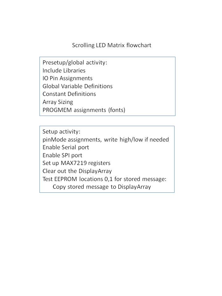
I did up a sort of flowchart showing the program execution summary.
The code itself is 21 landscape pages long, but this lets you see the idea behind it.
My code is way too long to post in this forum...could you give me your email possibly and I can send you a schematic capture and my code and see if you can see something I'm doing wrong .....making the LEDs have negative voltage,...
I already explained that.
If you have the meter- on a cathode that is driven high, and the meter+ on an anode that is driven low, you will see a negative voltage. Perfectly normal.
Well there's something up with either the code or the sequence I have the chips ....I dont understand why 2 of 3 matrices are full on .....all 64 LEDs on 2 and the next matrix is totally off.
Sequence will not matter - the code works the same whether the MAX7219's are connected or not. I did a lot of debugging just using Serial.print statements.
Any chance the display is just flipped end for end?
You have the serial monitor opened and a few characters entered?
So far I have 3 of 4 matrices wired up. I paid extra close attention to the columns and rows ......the first 2 are lit up totally....all 64 on the first 2. The third has none lit up and that's when I probed the anodes(+) and cathodes(-) in rows vs. Columns and saw the negative voltage. I opened the serial monitor and typed hello, but didn't see any effect......I still have the 4th to wire up.....ill update you on how that one reacts. Oh I don't doubt your code and debug, you had yours working........I think there maybe an issue with the integration of what I have and integrating yours in. I have a lot of lines that control an LCD , some buttons and LEDs too.....
I guess I should mention this: so I have ss0 plugged into max7219 #1 which in the 32x8 display is the farthest on the left...then 2 goes to the second matrix from left and then 3 second from right and 4 farthest matrix to the right. MOSI all parallel, SCK all parallel, each ss (load) hooked up to individual chips......the matrices are wired up correctly too.....I just wanted to make that clear....