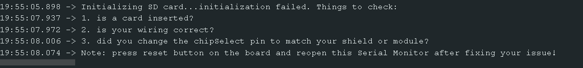
I’m having trouble getting the SD card reader to work with the Arduino Mega. I tested it with an Arduino Uno R3, and it worked fine. I’ve also tried multiple SD cards and even a different SD card reader, but I keep encountering the same issue: 'Initializing SD card... initialization failed.'
and the code iam using is from the library example :
#include <SPI.h>
#include <SD.h>

const int chipSelect = 53;

void setup() {
  // Open serial communications and wait for port to open:
  Serial.begin(9600);
  // wait for Serial Monitor to connect. Needed for native USB port boards only:
  while (!Serial);

  Serial.print("Initializing SD card...");

  if (!SD.begin(chipSelect)) {
    Serial.println("initialization failed. Things to check:");
    Serial.println("1. is a card inserted?");
    Serial.println("2. is your wiring correct?");
    Serial.println("3. did you change the chipSelect pin to match your shield or module?");
    Serial.println("Note: press reset button on the board and reopen this Serial Monitor after fixing your issue!");
    while (true);
  }

  Serial.println("initialization done.");
}

void loop() {
  // make a string for assembling the data to log:
  String dataString = "";

  // read three sensors and append to the string:
  for (int analogPin = 0; analogPin < 3; analogPin++) {
    int sensor = analogRead(analogPin);
    dataString += String(sensor);
    if (analogPin < 2) {
      dataString += ",";
    }
  }

  // open the file. note that only one file can be open at a time,
  // so you have to close this one before opening another.
  File dataFile = SD.open("datalog.txt", FILE_WRITE);

  // if the file is available, write to it:
  if (dataFile) {
    dataFile.println(dataString);
    dataFile.close();
    // print to the serial port too:
    Serial.println(dataString);
  }
  // if the file isn't open, pop up an error:
  else {
    Serial.println("error opening datalog.txt");
  }
}
Anyway, if it works fine with a Uno R3, then it almost has to be either the wrong pin for CS, or a power issue of some kind. Or, if you're using a breadboard, a bad jumper or connection.
Do you mind clarifying a bit more or refer me to a refrence so i can understand better, cause i tried setting the CS pin as output and it still fails to initialize, also i do not know what is SDCardChipSelectPin and what pin to choose for it.
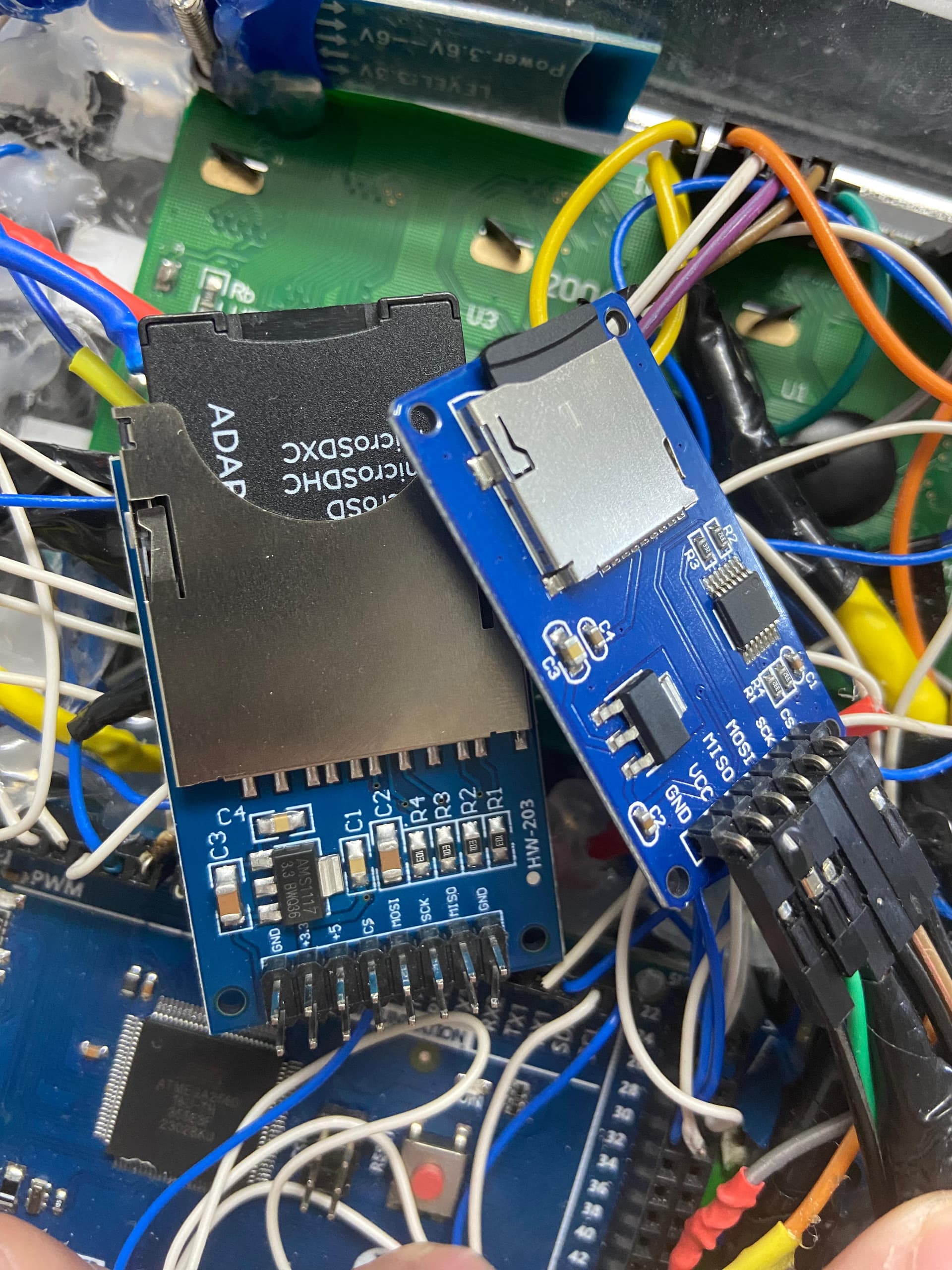
My understanding is that the Mega 2560 is a 5V device. If that's right, then you should be using the microSD module on the right, the one with the 14-pin level-shifter chip. And it should be powered with 5V at its Vcc header.
The HW-203 is for use with 3.3V microcontrollers. The four signal lines are passed through directly to the SD card, which is a 3.3V device.
If it still doesn't work using a library example, such as cardInfo.ino, then the card may be the wrong size, such as SDXC, or not formatted as FAT32, but more likely incorrect wiring or bad jumper wires. As far as I can tell, 53 is the correct pin for CS for the Mega.
I don't see any library examples setting any pin as output, so I don't know why that would be necessary.
Apparentlhe Arduino Mega 2560 SPI uses the pin 53 mode as an internal flag. It has to be in OUTPUT mode if any SPI is being used as Master. It is only the pin's mode that matters - so you can then cheat by using HIGH/LOW on pin 53 as a Chip Select for a Slave device. There are numerous online postings since about 2016 about this. I suspect I fell foul of that several years ago. eg ARDUINO MEGA 2560 Pin 53 (SS) problem - Using Arduino / Microcontrollers - Arduino Forum
I have a feeling that the SDCard reader also fails to initialise if there is no valid card in it.
The short set-up example I showed is an extract from my use of SPI SDCards on several Arduino Mega 2560 projects. The "SDCardChipSelectPin" name is whatever you choose for your Slave device CS pin. The name is a vestige of an original example by someone else many years ago.
I also use a different CS pin for a second device - an SPI screen - with the rest of the SPI pins common to the two devies viz SCK, MISO, MOSI.
I have found one quirk in a current implementation where pin 49 wouldn't work as a CS but 48 was ok. Not sure why that is so. Too many alligators in the IT swamp.
Here is the whole set-up function for my SDCard reader use.
#include <SPI.h>
#include <SD.h>

// this is the SPI slave indicator that must be set as Output if SPI is normal Master
#define SpiSsPinAssigned 53

//!! trying to use 49 for CS does not have any effect???
// 48 is ok
#define SDCardChipSelectPinAssigned 48

#define SDCardChipSelectPin SDCardChipSelectPinAssigned

#define SpiSsPin SpiSsPinAssigned

File ConfigFile;

void SDcard_setup()
{

  // Needs to guarantee 'SS' pin set to Output for running any (normal) SPI as Master
  // Can be used for other purposes - useful as a Chip Select pin
  pinMode(SpiSsPin, OUTPUT);
  pinMode(SDCardChipSelectPin, OUTPUT);


  // defaults to pre-compile configuration if unable to get a config file


  // if no SD card or config file will use pre-configured settings

  if (!SD.begin(SDCardChipSelectPin))
  {
    Serial.println(F("Could not initialize SD card"));
    return;
  }

   Serial.println(F("SD card OK"));


  InitialiseConfigFile();

  ConfigFile.close();

}
On closer inspection I agree with ShermanP. Does your UNO version power the SDCard from its 3.3v or 5v pin? The UNO 3.3v is very low current - so it seems an unlikely source.
I would suggest not using 3.3v on the Mega version - but connect using only the 5v supply pins on the Mega and SDCard module.
I would always use any 5v option on modules with a Mega. If a module only uses 3.3v - then I would think hard about the Mega 5v logic interface compatibility with them. My SDCard modules ony have a 5v supply pin - and they handle the level changes internally.
My pin 53 suggestions are based on examples from many years ago. Libraries may have changed since to make the Mega Master/Slave dependency less obvious.
The usual wires to connect Arduino devices are often the cheap short ones that come with attached single connectors: male/male; male/female; female/female. I have found they are potentially unreliable - either going open circuit or intermittent.
My problem with SPI CS on pin 49 was an intermittent wire that finally went open circuit after it had been flexed a few times.
Disconnecting the attached modules for their safety - a looping "blink" program for relevant pins indicates the problem. An oscilloscope (or simple LED/resistor) is used to see the expected level changes at the pin and at the far end of its wire. A meter then proves an open circuit wire. A failing pin usually can't be fixed - but the Mega might have another that can be used instead.***
***Occam's Razor does not necessarily apply - you may have several root causes each giving the same apparent symptom. My SPI screen works on its long cable - but its added capacitance loading stops the close-connected SPI SDCard reader from working. Connect screen on short wires - no problems.
Somewhere I saw where a guy got SPI to work by using the ICSP headers. Apparently it was a clone board, and one of the SPI pins along the side wasn't actually connected to the chip - a broken trace maybe, or just designed that way. You could check that by running the Blink example on the four SPI pins. But this would very much be a long shot. Much more likely to be a bad connection or bad jumper.
I use the ICSP header for an "add-on" SPI SDCard reader on some of my older Arduino designs - with a dangling lead to a selected CS pin. I once had a problem with a NANO - as the ICSP socket pin-out was rotated 180 degrees from normal. Most of the online pictures of Arduino boards are devoid of any explicit ICSP socket pin annotation.
My Arduino Mega 2560 PRO board has almost no indication of the ICSP pin 1 position. The board is so compact that there is little room for easily read legends. I have just upgraded an old implementation by shoe-horning an Arduino 2560 PRO on a daughter board into a NANO socket. The double-row pins are a pain. Had to source long pin sockets and use wirewrap for cross-connections. One of those "will be quick" naive assumptions. A new motherboard design with a full Arduino 2560 would have been better and probably easier..
I now use a fine "paint" marker on every new board to make ICSP pin-out very clear for any future use.