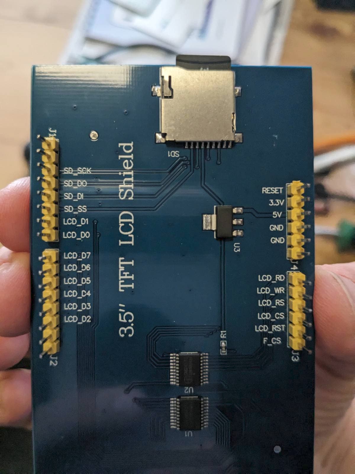
According to the positioning of the Reset, 3.3V, 5V, GND etc. pins on the right side and the D2-D7 Pins right below the SD pins should be digital 10-13. I've tried every pin in that range in SD.begin() but with no luck. Most guides say to enter the "CS Pin" here, but none of my SD pins is labeled as CS, so which one is it?
The SD Card is a 32GB card, formated to FAT32 via Windows Explorer. My goal would be to load a jpg (or bmp) file as splashscreen and a txt to Serial Monitor as help file.
PS: The screen itself is working just fine with MCUFRIEND_kbv and Adafruit_GFX. I'm currently only trying to get the SD reader to work.
The SPI connections have to be modified.
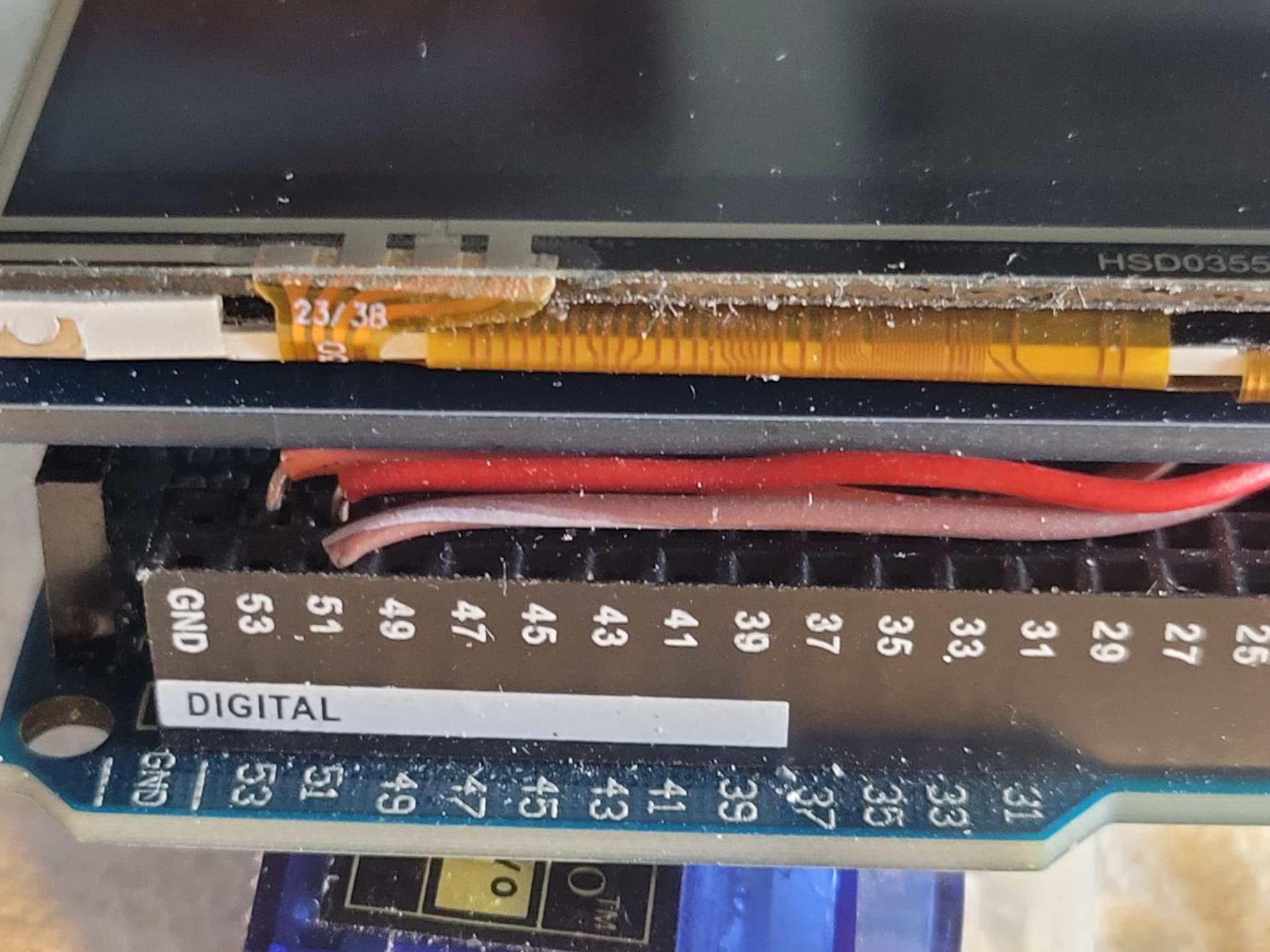
The shield is wired for an Uno. Modification necessary to use with a Mega. There are a couple of ways to do it. I prefered to bend the SCK, MOSI, MISO pins up and connect with jumpers to pins 52, 51, 50.
You might want to double check that that shield has level shifters between the SD_SCK, SD_DI and SD_SS pins and the uSD. I've found that often there aren't any, which exposes the uSD card to 5V level signals from the Uno or Mega. And from looking at your photo, I'm pretty sure that's the case with your shield.
So, in short - better don't use it if it's not really necessary, wich isn't the case in this project Thanks nevertheless for the fast responses, I think I'll go with external SD reader modules for future projects.
Edit: Concerning the level shift: I'm a little rusty on my electronics expertise (learned all of that years ago in school), but there's a line coming from the SD Reader over a modulator U3 to a resistor R1. Shouldn't that be a voltage divider?